22
You can press the “INC” or “DEC” button to set the period of soft start. There is 1-9 seconds available in setting.
Press the “FUNC” button to store the data when the period is set. The Digital Display will indicate “PC”.
(Factory set is 3 seconds)
11. Set the Fast Running Period (FRP) to Achieve Soft Stop Function (SPP)
When the Digital Display indicates “PC”, the Fast Running Period for opening or closing gate is adjustable by
pressing “INC” and “DEC” buttons respectively, and the Soft Stop Function is achieved simultaneously.
The Soft Stop means the gate opener runs at slow speed during the last period before the gate completely
closes. The Soft Stop Period is unavailable by direct adjust but available through adjusting the Fast Running
Period.
There are two running speeds designed in program, i.e. Fast Running Speed and Soft Running Speed. The
Fast Running Period is adjustable from 1 to 28 sec. Factory default setting is 15 sec.
Since the GATE OPENING OR CLOSING RUNING PERIOD (GRP) = SOFT START PERIOD (STP) + FAST
RUNNING PERIOD (FRP) + SOFT STOP PERIOD (SPP), the SPP could be extended by shortening the FRP
when the GRP and STP are fixed. In other words, SPP = GRP–STP–FRP.
Similarly, the Soft Stop Period (SPP) can be shortened through extending the Fast Running Period (FPP).
E.g.
When the Soft Start Period (STP) is set at 3 sec, and the GRP is 23 sec (you can
calculate
the GRP
period by yourself, from” the arm actuator starting to move
on the fully open position
” to “the arm arriving
at the fully close position
”), how can we get 4 sec of Soft Stop Period (SPP) to meet the requirement? The
answer is clear, i.e. we may set the Fast Running Period (FRP) at 16 sec (23 – 3 – 4 =16 sec).
12. Return to Factory Set
When the Digital Display indicates “Pd”, press and release the “INC” or “DEC” button. All data will return to
factory set, the Digital Display indicates “dF”.
13.
If all of data is set and no other change needed, press “FUNC” Button. “- -” appears on the Digital Display,
and the opener enters standby mode.
Indicate Illustration on the Digital Display When Gate Opener is Running
The left image on Digital Display symbolizes motor of gate opener
2
when the gate opener is running. The right
image on Digital Display symbolizes motor of gate opener
1.
When the motor is run to gate -open direction or gate -close direction, the image on Digital Display indicates “n”
or “u” respectively. When the motor is not running, the Digital Display indicates
“- -”.
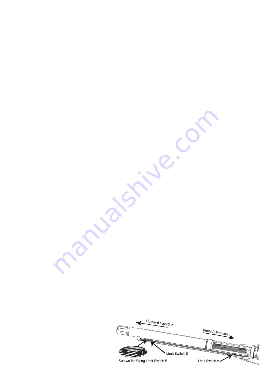
Adjusting the Limit Switch
Note: Before adjusting the limit switch, refer to the chapter of “Install the Opener on the Gate”, and make sure that
the rod is fully retracted when the gate is in the fully open position (for Pull-to-Open installation), or in the fully closed
position (for Push-to-Open installation). Make sure that currently the rod is fully retracted.
Note: The position of Limit Switch A was fixed in factory, do not adjust it again.
1 For Pull-to-Open Installation, adjust the limit switch B to determine the closed position:
Turn on power to operate the gate opener, then the arm extends to close the gate.
If the arm closes over the desired closed position, press the remote control to stop the opener. Use a screwdriver to
loosen the screw of the limit B, slightly slide the limit switch B
inwards.
If the arm closes halfway and fails to get to the
desired closed position, slightly slide the limit
switch B
outwards.
Please
repeat
the above steps, until the arm
could arrive and automatically stop at the
desired close position. Then tighten the screw
Summary of Contents for MT9012
Page 6: ...3 MT9012 Parts List Extra parts for rounded gate post...
Page 18: ...15 Connecting of the Control Board...
Page 28: ...25 Quick Setting Guide...
Page 29: ...26...
Page 30: ...27...
Page 31: ...28...


