


19-23
19 TOP FIELD MODE
19.5.5To Transfer Coordinate Data
Setting Transmission Protocol
Set items for transmission protocol are as follows according to the format.
GTS FORMAT
SSS FORMAT
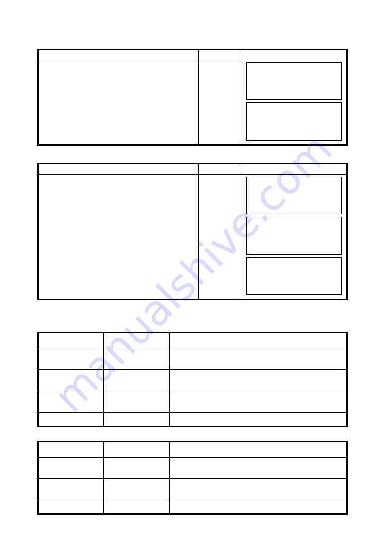
Operating procedure
Operation
Display
1
Select
{F2}
(DATA TRANSFER).
Data transfer corresponds to the following two
types of transmission formats:
F1: GTS FORMAT
F2: SSS FORMAT
{F2}
Operating procedure
Operation
Display
Always check transmission protocol before
performing data transfer.
1
Select the transmission format to use.
{F1}
or
{F2}
2
Select
{F3}
(COMM. PARAMETERS)
{F3}
Item
Selecting Item
Contents
Protocol
[ACK/NAK],
[ONE WAY]
Setting Protocol
[ACK/NAK] or [ONE WAY] communication
Baud rate
1200, 2400, 4800,
9600, 19200, 38400
Setting transfer speed
1200/2400/4800/9600/19200/38400 baud
Char. / Parity
[7/EVEN], [7/ODD],
[8/NON]
Setting data length and parity.
[7 bit, even], [7 bit, odd], [8 bit,none]
Stop Bits
1, 2
Setting Stop 1 bit or 2bits
Item
Selecting Item
Contents
Baud rate
1200, 2400, 4800,
9600, 19200, 38400
Setting transfer speed
1200/2400/4800/9600/19200/38400 baud
Char. / Parity
[7/EVEN], [7/ODD],
[8/NON]
Setting data length and parity.
[7 bit, even], [7 bit, odd], [8 bit,none]
Stop Bits
1, 2
Setting Stop 1 bit or 2bits
4.EDIT POINT
5.DATA TRANSFER
[4] [5]
↑
DATA TRANSFER
F1:GTS FORMAT
F2:SSS FORMAT
DATA TRANSFER
F1:GTS FORMAT
F2:SSS FORMAT
DATA TRANSFER
F1:SEND DATA
F2:LOAD DATA
F3:COMM. PARAMETERS
COMM. PARAMETERS
F1:BAUD RATE
F2:CHAR./PARITY
F3:STOP BITS


