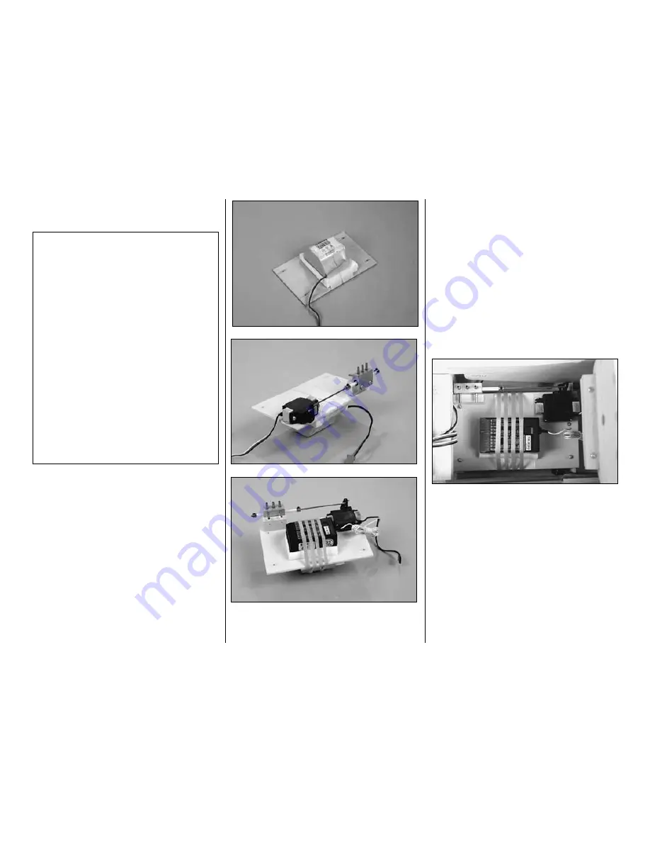
Mount the receiver and battery pack
There is more than one way to mount your receiver
and battery pack. Some modelers have developed
their own proven methods. However you decide to
mount your receiver and battery, they should be
cushioned with R/C foam rubber and securely
mounted so they cannot come loose upon a rough
landing or abrupt maneuvers. Simply stuffing them
into place with foam is not recommended. Space is a
little tight inside the Focke-Wulf fuselage, but there’s
plenty of room for all the components if you plan
carefully. The following steps illustrate the way we
mounted the receiver, battery pack and air valve
setup in our proto.
❏
1. Make a 3" x 5"
receiver mounting plate
from
1/8" plywood (not included). Mount the battery pack,
receiver and retract and air valve system to the plate.
On our prototype we mounted a 6 volt battery pack,
cushioned with a piece of 1/2" R/C foam rubber, to
the top of the plate and secured it with nylon filament
tape. Connect the retract servo to the air valve
according to the manufacturer's instructions (CJM
system shown). The air valve was mounted to a
basswood block. The receiver, also cushioned with
1/2" R/C foam rubber, was secured to the platform
with two #64 rubber bands.
Note:
We used a 6 volt,
1,000 mAh battery pack in our prototype. Whatever
type of pack you use, a larger capacity pack, such as
800 mAh or 1,000 mAh, is recommended if you have
built your model with flaps and retracts.
❏
2. Glue two 1/4" x 3/8" basswood rails (not
included) to formers F-4 and F-5 where shown on
the plan. Mount the platform to the rails with four #2
x 3/8" screws (not included).
❏
3. Mount the on/off switch, charge jack (if you use
one) and the retract air filler valve in a location that is
easily accessible, that will not interfere with anything
inside the model and is out of the way of engine
exhaust residue. If you mount any of those items
directly to the fuse sheeting, first glue a sheet of
leftover ABS or 1/32" plywood to the inside of the
sheeting in those areas.
Some modelers prefer to mount the receiver,
battery pack and associated hardware (on/off
switch, charge jack, air filler valve for retracts, etc.)
after
the model is covered. One advantage to
doing this is that those components can be
positioned where necessary to minimize
additional weight that may be required to achieve
the correct C.G. If, for example, while balancing
the model (
see
Balance your model
on page 57),
you find that it is tail heavy, you could mount the
battery pack in a location ahead of the C.G., so
that no additional nose weight will be required.
Our flying prototype, with the O.S. Max .61 FX
engine, required no additional ballast to achieve
the correct C.G. with the battery pack and receiver
mounted where shown in the following steps. If
you are using a similar setup, you could go ahead
and mount your receiver and battery pack where
shown and rest assured that little or no additional
nose or tail weight will be required. If, however,
you prefer to mount these components after the
model is covered, return to this section when you
are ready.
-51-


