7. If an automatic oiler is not used, add a few drops of Pneumatic Tool Oil to the
airline connection before use. Add a few drops more after each hour of
continual use.
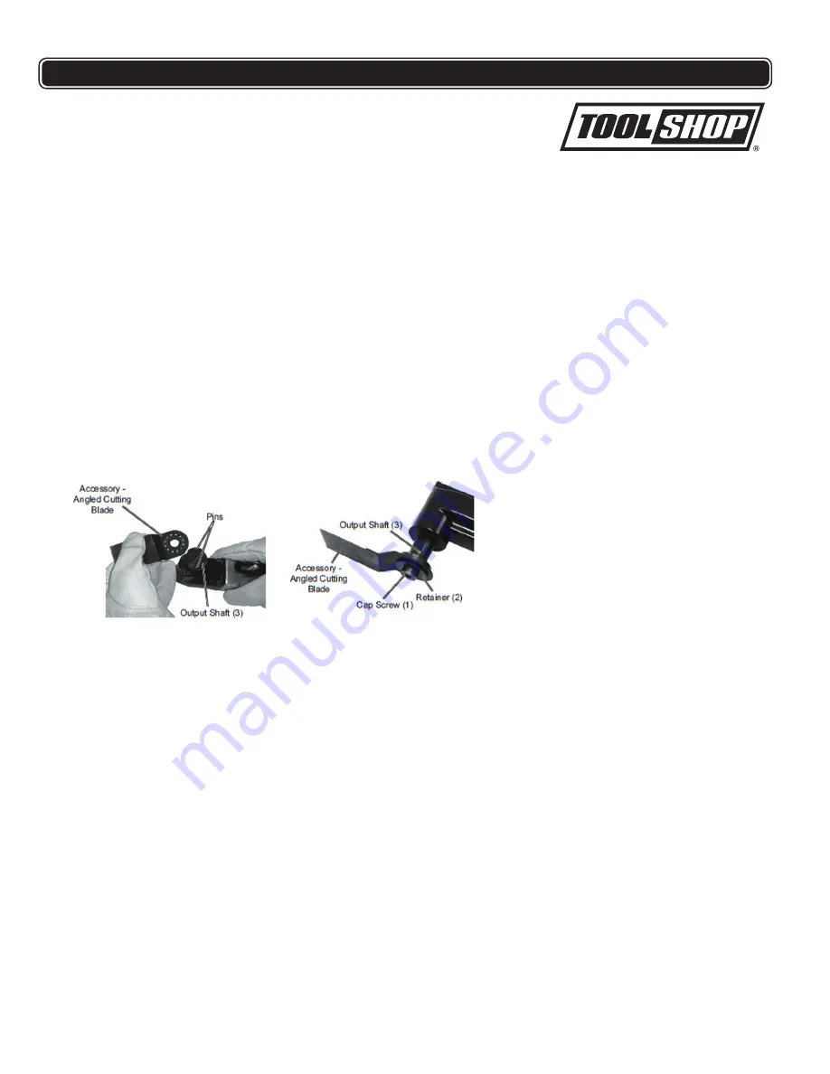
8. To install an accessory:
a. While the air hose is disconnected from the tool, hold the Output Shaft (3)
with a 13mm wrench (sold separately), and unthread the Cap screw (1)
using the Hex Wrench (43). Remove the Cap Screw and Retainer (2).
b. Install the desired accessory in any one of seven orientations by aligning two
of the holes in the accessory over the two prongs on the Output Shaft (3).
Note: When attaching the Angled Cutting Blade Accessory, orient the accessory
as shown above so the Cap Screw (1)will be out of the way when working.
c. Replace the Retainer (2) and Cap Screw (1) while holding the blade. Hold
the Output Shaft (3) with the hex wrench (43), then tighten securely using
the Hex Wrench (43).
Note: For sanding, first attach the Sanding Pad to the tool, then align a sheet of
sand paper over the pad and press into place.
d. Attach the air hose from the air source. While holding the air tool firmly in
one hand and the other safely out of the way of the accessory, turn the air
souce on.
9. To begin use, push the Safety Catch (38) forward while squeezing the Trigger
Lever (41). A stable two-handed grip on this tool is best.
10. Adjust pressure on the Trigger Lever to change the speed of the tool.
11. Address the material with a smooth steady stroke of the tool.
Note: Do not force the tool. Let the tool do the work.
If the tool requires more force to accomplish the task, verify that the tool
receives sufficient unobstructed airflow (CFM) and increase the pressure (PSI)
output of the regulator up to the maximum air pressure rating for this tool.
Figure 3
5
OPERATING PROCEDURES
OPERATION:
Turn the tool off, detach the air supply, safely discharge any residual air
pressure in the tool, and release the throttle and/or turn the switch to its off
position before assembling or making any adjustments to the tool
WORK PIECE AND WORK AREA SET UP
1. Designate a work area that is clean and well-lit. The work area must not allow
access by children or pets to prevent distraction and injury
.
2. Route the air hose along a safe path to reach the work area without creating a
tripping hazard or exposing the power cord to possible damage. The power
cord must reach the work area with enough extra length to allow free movement
while working.
3. There must not be hazardous objects, such as utility lines or foreign objects,
nearby that will present a hazard while working.
4. You must use personal safety equipment including, but not limited to, ANSI-
approved eye and hearing protection, as well as heavy work gloves.
5. Before beginning work, protect area from sparks and debris that will fly off the
work surface.
6. Remove the Plug (28) from the Air Inlet and thread the Coupler Plug (44) onto
the tool using three to four wraps of thread sealing tape (sold separately).
12.


