background image

OPEN RECOVERY LID

1.     Release both latches

"A"

on recovery tank lid.

(SEE BELOW)

2.    Rotate lid fully open.

CLEAN "DRAIN SAVER"

    WITH RECOVERY LID OPEN & TANK FULLY DRAINED

1.     Remove 2" squeegee intake hose

"A"

 from

"Drain Saver"

 strainer

"B"

 (SEE

BELOW

)

2.    Remove stainless screen, dispose of debris.

3.    Rinse screen with fresh water from the outside

       to the inside holding screen upside down.

       This will allow for better cleaning.

4.    Replace the screen into the bracket.

5.    Replace 2" squeegee intake hose.

FLUSH RECOVERY TANK

1.  Rinse the recovery tank after every use. This will

      prevent heavy buildup on the bottom of the tank,

      foul odors,  and clogging of the drain hose.

      (SEE

BELOW

)

3.  After rinsing, reattach drain hose "

B"

on hook.

      (SEE BELOW)

CLEAN VAC SCREEN

WITH RECOVERY LID OPEN & TANK FULLY DRAINED

1.     Remove vac screen retaining clip

 "A

".

(SEE

BELOW

)

2.    Pull vac screen and float ball assembly

 (B)

 off

       the vac box.

3.    Rinse with hot water.

4.    Dry thoroughly.

5.    Replace vac screen onto box.

6.    Replace and tighten retaining clip.

A

B

A

B

PAGE 17

A

B

Summary of Contents for mini mag series

Page 1: ...R P S Corporation Phone 1 800 450 9824 P O Box 241 Fax 1 866 632 6961 Racine Wisconsin 53401 MINI MAG Operator Manual 2009 Version 1 0 ...

Page 2: ...ion and function of the machine The MAINTENANCE section contains preventative maintenance to keep the machine and its components in good working condition They are listed in this general order Batteries Scrub Brushes Adjusting Squeegee Service Schedule Machine Trouble Shooting The PARTS LIST section contains assembled parts illustrations and corresponding parts list The parts lists include a numbe...

Page 3: ......

Page 4: ......

Page 5: ...SOLUTION FLOW CURTAINS DRAINING TANKS CLEANING RECOVERY TANK TIP TANK RAISE LOWER SQUEEGEE ADJ DECK HEIGHT VAC MOTOR SOLUTION FILTER CHARGING BATTERIES ON BOARD BATTERY CHARGER OPTIONAL MAINTENANCE STORING MACHINE PREVENTATIVE MAINTENANCE RECORDS LCD SCREEN MENU DISPLAY S TROUBLESHOOTING PAGE 1 PAGE 2 PAGE 3 PAGE 4 PAGE 5 PAGE 6 PAGE 7 8 PAGE 9 PAGE 10 PAGE 11 PAGE 12 PAGE 13 15 PAGE 16 PAGE 17 PA...

Page 6: ...____________________________ City State Zip ______________________________________________________________ Phone Number _____________________________________________________________ This operator and parts manual should be considered a permanent part of the unit and should remain with the unit at all times This operator and parts manual covers all the Mini Mag series scrubbers You may find descrip...

Page 7: ...ation Double Scrubbing Squeegee Delay Vac Timer Recovery Tank Draining and Cleaning Vac Screen Removal and Cleaning Shroud and Pad Removal Shroud Adjustment Solution Valve and Filter Operation removal and cleaning Drain Saver Feature Charging Operation Seat and Steering Wheel Adjustment LCD Screen Display Operation 3 Hour Meters keyswitch brush traction drive Tank Tilt Back Feature Parking Brake O...

Page 8: ...utomatic DRIVE SYSTEM Standard Drive Brush Drive 0 5 hp all gear sealed Forward Speed 0 230 ft min 4 mph 0 230 ft min 4 mph Reverse Speed 0 130 ft min 2 mph 0 130 ft min 2 mph SOLUTION SYSTEM Solution Tank Cap 17 gallons 17 gallons Solution Flow Rate 0 1 0 gpm 0 1 0 gpm Solution Filter Stainless Inline Stainless Inline RECOVERY SYSTEM Recovery Tank Cap 17 gallons 17 gallons Vac Power 0 75 hp 0 75 ...

Page 9: ...RIAL 50000 REF CYL DOOR ASSEMBLY Kit Includes 1 Rear Blade 1 Front Blade and 2 Backup Wheels with hardware Note Size is stamped into the top of the painted steel squeegee blank on 32 35 squeegees Note The Squeegee is designed for narrow isles and may not have the same water control around tight turns as the larger squeegees EXTRA PAD DRIVER RETAINING CLIP 40 433 BRUSH REPAIR KIT 40 423 REPLACEMENT...

Page 10: ...r commercial use It is designed to be used on hard floors in an indoor environment with the recommended pads or brushes 1 DO NOT OPERATE UNIT Unless trained and authorized Unless operator manual is read and understood If unit is not in proper operating condition 2 WHEN OPERATING UNIT Remove loose objects from the floor that may be projected from the revolving brushes Keep hands and feet away from ...

Page 11: ...r outlets May result in serious injury PAGE 6 WARNING Hazardous voltage Shock burns or electrocution can result Always disconnect the batteries before servicing machine WARNING Batteries emit hydrogen gases Explosion or fire can result Keep sparks and open flames away WARNING Charge unit in a well ventilated area and keep battery compartment open when charging Explosion or fire could result WARNIN...

Page 12: ...PAGE 7 MACHINE CONTROLS AND FEATURES 1 2 11 10 8 7 6 3 4 5 23 24 28 29 30 31 32 33 26 34 35 36 37 38 41 39 44 45 43 25 40 42 22 26 27 20 21 9 14 18 16 15 17 13 12 6 10 11 21 20 19 22 ...

Page 13: ...IAL NUMBER PLATE Machine identification 22 SPEED CONTROL KNOB Controls the speed of the Traction Drive Turn counter clockwise to reduce speed 23 TRACTION DRIVE Propels machine forward backward 24 SOLUTION FLOW VALVE Controls solution flow rate 25 SOLUTION FILTER Filters water solution prior to scrubbing 26 WALL ROLLERS Helps protect machine when scrubbing near walls 27 PAD ASSIST DRIVE ADJUSTMENT ...

Page 14: ...wo knobs B on the squeegee and slide them into the slots in the squeegee mounting plate SEE BELOW ATTACHING SQUEEGEE 1 Lower the squeegee mounting plate by rotating the lift lever A clockwise SEE BELOW 4 You may have to adjust the squeegee pitch SEE ADJUSTING SQUEEGEE ON NEXT PAGE BATTERY CABLE CONNECTIONS 2 Tighten the two knobs and connect the vacuum hose C from the machine to the squeegee SEE B...

Page 15: ...GEE BLADES FOR SAFETY Before leaving or servicing machine stop on level surface turn off machine and remove key 1 Remove the squeegee assembly from the machine Remove blade retainer strap and remove squeegee blade 2 Rotate the squeegee to new edge position or replace as required 3 Install blade on the locating pins of squeegee assembly 4 Install squeegee retainer strap 5 Fasten and lock knobs REMO...

Page 16: ... Pad installation attach pads to pad drivers before connecting drivers to motor hub center clip C should click twice SEE BELOW 6 Attach brushes or pads to motor hubs Squeeze the scissor locking device and lift brush up on to the motor drive hub Make sure the scissors close and lock once the brushes are on SEE BELOW INSTALLING DISK PAD DRIVER OR BRUSH C SCRUB BRUSHES There are many different types ...

Page 17: ...1 Turn on machine power 2 Raise the scrub deck by depressing the brush switch O to the up and off position and turn machine power back off 3 Disconnect batteries 3 Remove side access door on each side of scubdeck by depressing latch button A and unscrewing thumb screw B SEE BELOW 7 Brush driver shown misaligned SEE BELOW 8 Brush driver shown properly aligned SEE BELOW 9 To adjust the tension of th...

Page 18: ...in the recovery tank If excess foam begins to develop pour a recommended foam control solution into the recovery tank Foam is usually an indication of excessive soap 3 Always operate at lower speeds when scrubbing around walls and objects You should reduce the speed to maintain control when turning 4 If squeegee starts to streak raise and wipe the blades with a clean cloth If the problem continues...

Page 19: ... machine let go of the green control button F SCRUB ONLY BRUSH DRIVE MACHINES SEE BELOW 1 Turn on machine power switch A make sure the PAD ASSIST adjustment knob B is at a low setting 2 Lower scrub head to the floor use the top half of the brush switch D 4 Turn on the solution switch E 5 Begin scrubbing by depressing the green control button F on the handle bar Adjust the PAD ASSIST adjustment kno...

Page 20: ...ACTION DRIVE MACHINES SEE BELOW 1 Turn on machine power switch A make sure the speed control knob B is at it s lowest setting 2 Lower scrub head to the floor use the top half of the brush switch D 4 Turn the solution flow adjustment knob E to regulate the amount of solution flow 5 Begin scrubbing by depressing one of the green control buttons D on the handle bar Adjust the speed control knob B to ...

Page 21: ...NG RECOVERY TANK Always empty recovery tank when refilling the solution tank You can refill the solution tank while the recovery tank is draining To drain the recovery tank remove drain hose A from hook at rear of tank and unscrew cap SEE BELOW NOTE LEAVE RECOVERY LID OPEN WHEN DRAINING TANK ADJUST CURTAINS WIPERS 1 For Jaw curtains release latch A and remove pin B on front of jaws to open jaws SE...

Page 22: ...ning 4 Replace the screen into the bracket 5 Replace 2 squeegee intake hose FLUSH RECOVERY TANK 1 Rinse the recovery tank after every use This will prevent heavy buildup on the bottom of the tank foul odors and clogging of the drain hose SEE BELOW 3 After rinsing reattach drain hose B on hook SEE BELOW CLEAN VAC SCREEN WITH RECOVERY LID OPEN TANK FULLY DRAINED 1 Remove vac screen retaining clip A ...

Page 23: ...p not shown SEE BELOW CAUTION Casters need to be swiveled back B as shown otherwise machine will tip SQUEEGEE UP 1 To raise the squeegee off the floor rotate squeege lift lever A counter clock wise all the way to the left SEE BELOW SQUEEGEE DOWN 1 To lower the squeegee to the floor rotate squeegee lift lever B clockwise all the way to the right Vac motor will turn on automatically Use with remote ...

Page 24: ...system has a INLINE FILTER A to filter out cleaning solution prior to scrubbing SEE BELOW CLEANING SOLUTION FILTER SEE BELOW 1 To clean the SOLUTION FILTER Unscrew the clear cap A from housing B and remove the STAINLESS STEEL screen C 2 Rinse any debris from the screen with clean water 3 Reinstall screen and screw cap back on tightly PAGE 19 B C A 1 To adjust deck height for brush clearance loosen...

Page 25: ...ater level through pro eye window in each battery SEE TOP PICTURE Do not charge the machine unless the water is slightly higher than the plates If needed add enough distilled water to just slightly cover the plates Be careful not to over fill Batteries can overflow during charging Replace caps before charging 5 With the red 50 charger plug connected to the machine FIRST SEE MIDDLE PICTURE plug the...

Page 26: ...nt charger programming these parameters depend on internal dipswitch configuration The following details are shown 1 SPE 2 Version of software installed in the charger 3 Battery voltage 4 Charging current 5 Number of charging curve selected see explanation at bottom of following page 6 The message Acd if programmed charging curve is for POWERCAT wet Lead Acid batteries or GEL if programmed chargin...

Page 27: ... exceeds normal limits This usually indicates a sulfated damaged battery Sometimes a second charge attempt can be successful in recharging the battery pack The display of the message SCt indicates safety timer operation The message Srt will be displayed in case of internal short circuit DIP SWITCH CONFIGURATION Through the set of 8 dip switches it is possible to change the charging curve for POWER...

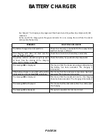
Page 28: ...cessary CONTROLS see figure behind the cover 1 Three digit display symbol 1 to view A the charging current U the battery voltage h the charging time C the charging ampere hours AH E the energy used KWh 2 Button for the Selection of the display mode 2 A U h C E After about 10 seconds the display returns to the visualization of the charging current 3 Red control indicator 3 when it is on the chargin...

Page 29: ...even 15 hours from the starting of the charging cycle and the display shows E03 Check the battery for possible faulty components The message E01 is displayed This means that the maximum voltage admissible by the battery has been exceeded The charging is interrupted If the battery charger is provided with a safety thermostat and the message E02 is displayed This means that the maximum temperature h...

Page 30: ...l in each cell of the batteries and fill as needed Always usedistilled water to refill batteries Batteries should be filled approximately 3 4 to 1 above the plates Overfilling will cause the batteries to leak during charging The charging process creates gas bubbles inside the battery which effectively increases the volume of the electrolyte 2 Clean battery tops to prevent corrosion 3 Rotate brushe...

Page 31: ...k Battery Cable and Terminal Condition NOTES BRUSH CONDITION Scrub Brush Fiber Length Rotated Brushes Brush Drive Sockets Good Worn Needs Replacement Drive Hubs Good Worn Needs Replacement CHECK OPERATION AND CONDITION OF IN SPEC REPAIR PROBLEM Main Power Switch or Key Switch Handle Bar Switches Speed Potentiometer Reverse Switch LCD Display Page Switch Brush Pressure Switch Brush Pressure Manager...

Page 32: ...ueegee Knob Threads Squeegee Pivot Points Brush Head Pivot Points VISUALLY INSPECT IN SPEC REPAIR PROBLEM Solution Tank Condition Recovery Tank Lid Condition Drain Saver Vacuum Float Vacuum Motor Brushes Vacuum Hoses Vacuum Filter Solution Hoses Squeegee Tool and Throat Squeegee Blades Blade retainers Hardware Squeegee Wheels Brush Skirts Brush Motor Brushes Brush or Pad Driver Condition Drive Whe...

Page 33: ...ansport hour meter Tells you the total hours the drive system has been used 8 Error warning symbol Indicates when there has been a diagnostic code error 9 Diagnostic code When the machine has detected an error it will display the warning symbol and a diagnostic code which tells you what s wrong 10 Water on Indicates the solution flow is on 11 Solution level Indicates the gallons per minute G P M 0...

Page 34: ...below the dashboard This switch will turn off the traction drive and brushes as a safety feature while the charger is plugged in The switch may be stuck or the plug twisted at an angle engaging the switch This code will also flash if the wiring becomes very wet In this case either wait until the wiring dries out or call a technician 2 7601 AND 7602 ERROR Pads or brushes current over load This can ...

Page 35: ...ROTTLE ERROR You pressed the drive button before turning on the key Turn off the key release the drive button and try again 7 2C00 AND 2C01 ERROR Low voltage warning Voltage has dropped down below the minimum required to operate the machine If you wait a few minutes the batteries may coast up a bit in voltage allowing you to drive very slowly to the recharge station 8 7802 ERROR The traction motor...

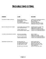
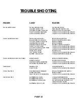
Page 36: ...NK LOW FLOW KNOB TURNED DOWN SOLUTION FILTER CLOGGED SOLUTION LINE CLOGGED SOLUTION VALVE CLOGGED SOLUTION CONTACT LOCAL SERVICING DEALER SEE CHARGING BATTERIES REPLACE BATTERY TIGHTEN LOOSE CABLE WAIT 5 MINUTES FOR AUTO RESET DETERMINE CAUSE AND CORRECT DEPRESS BUTTON ON HANDLE BAR RESET REDUCE PRESSURE DETERMINE CAUSE AND CORRECT CONTACT LOCAL SERVICING DEALER CONTACT LOCAL SERVICING DEALER REPL...

Page 37: ...ERIES STILL DOWN BATTERIES LOW ON WATER BATTERIES OVER CYCLED SOLUTION FILL SOLUTION TANK TURN SOLUTION SWITCH ON REMOVE AND CLEAN SCREEN CONTACT LOCAL SERVICING DEALER CONTACT LOCAL SERVICING DEALER EMPTY RECOVERY TANK REMOVE SCREEN AND CLEAN REMOVE DEBRIS REMOVE DEBRIS ROTATE OR REPLACE BLADES CONTACT LOCAL SERVICING DEALER CONTACT LOCAL SERVICING DEALER CONTACT LOCAL SERVICING DEALER TIGHTEN PL...

Page 38: ......

Reviews: