


4
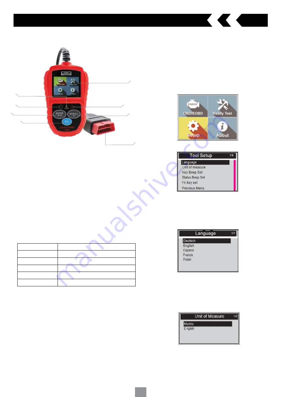
3.1 Scan tool description
3. Using the scan tool
3.2 Specifications
Screen
2.0” TFT colour display (220 x 176 dpi)
External Power
8.0 to 16.0 volts, provided via vehicle battery
Operating temperature 0 to 60 °C (32 to 140 °F)
Storage temperature
-20 to 70 °C (-4 to 158 °F)
Dimensions (mm)
Length 124 x Width:72 x Height 18
GW
0.21kg
3.3 Navigation Characters
Characters used to help navigate the scan tool
#
- Identifies the control module number from which data is retrieved
Pd
- Identifies a pending DTC when viewing DTC’s
3.4 Keypad
Use only a mild non-abrasive detergent and a soft cotton cloth when
cleaning keypad and screen. Do not use solvents such as alcohol or
automotive degreasers. Do not soak the keypad
3.5 Power supply
The power source from the vehicle will supply the scan tool via the data link
connector
3.6 Tool Setup
The scan tool allows you to make the following personalised settings
1 Language
- Select the preferred language
2 Unit of measure
- Set the unit of measure to Metric or Imperial
3 Key Beep Set
- Turns on/off key-press beep
4 Status Beep Set
- Turns on/off the I/M Readiness Status beep
5 Fn Key Set
- Set the One-Click-Quick Function Key including usual
Datastream, All Datastream, I/M readiness status and read code
Main Menu
When the scan tool is turned on, it will display the main screen
Tool Setup Menu
1 Language
NOTE:
Language is set in English by default
From the Tool Setup menu scroll through and highlight Language and press
the ‘ENTER’ key
Scroll down the Language menu and highlight the preferred language
Press the ‘ENTER’ key to save your selection and return the to
previous screen
2 Unit of Measure
NOTE:
Unit of measure is set to Metric by default
From the Tool Setup menu scroll through and highlight Unit of Measure and
press the ‘ENTER’ key
Highlight to select Metric or English as preferred unit
Press the ‘ENTER’ key to save your selection and return to the previous
screen
1 OBD II CONNECTOR
- Connects the scan tool to the vehicle’s Data Link
Connector (DLC)
2 LCD DISPLAY
- Indicates test results
3 GREEN LED
- Indicates that engine systems are running normally
4 YELLOW LED
- Indicates there is a possible fault. A “Pending” DTC is
present and/or some of the vehicle’s emission monitors have not run their
diagnostic testing
5 RED LED
- Indicates there is a fault in one or more of the vehicle’s
systems. The red LED is also used to show that DTCs are present
6 Fn (one-click function) key
- Shortcut for 4 quick function including I/M
readiness status, read code, usual Datastream and all Datastream
7 ENTER/EXIT KEY
- Confirms a selection (or action) from a menu or return
to previous menu
8 SCROLL KEY
- Scrolls through menu items
2 LCD DISPLAY
5 RED LED
8 SCROLL KEY
1 OBD II
CONNECTOR
3 GREEN LED
7 ENTER/EXIT KEY
6 Fn
4 YELLOW LED


