Communication manual TOHO ELECTRONICS INC.
DWG.No. 4B-6829-A
- 20 -
5.2.3.
Explanation About Codes
■
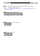
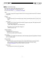
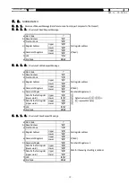
The following codes from (a) Start Code, (b) Slave Address up to (j) Error Number will be expressed in ASCII code:
■
See “
" or the detail about ASCII codes.
■
For the conversion into ASCII code,
See “
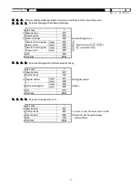
Structure of Request Message (Data Transmission from Upper Computer to This Product)
” for details.
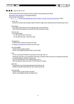
(a) Start Code
It is a code that is necessary for the receiving side to detect the start of the message. It shall be attached to the start of the character string to be sent.
(b) Slave Address
It is an address of the device that will be communicated by the upper computer (this product).
Address in the response message form this product indicates the source of response message.
(c) Function Code
Enter the code 03H or 10H.
・
03H: If the data is to be read from this product
・
10H: If the data is to be written or saved into this product
(d) Register Address
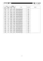
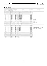
Specifies the position of data to be read or written with 2bytes.
See “
” for the address of each command.
(e) Number of Registers
Specifies the number of registers that writes.
Since the number of registers of this product is fixed to 2, set it to “0002H.”
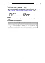
(f) LRC
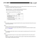
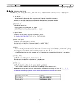
It is an error-checking code for the detection of a possible error in the message. It sends LRC.
LRC that is used in this product is a value where all data in the message, except for start code and end code, are summed upwithout performing a
carry over and treated the sum total as the complement of 2.
Any portion that is expressed as “1” and “B” shall
be considered as “1BH.”
If 12H was computed as an error number, attach “1” and “2” at the end of the message.
(g) End Code
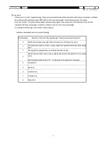
It is a code that is necessary for the receiving side to detect the end of the message.
CR(0DH) and LF(0AH) shall be attached at the end of the character string to be sent.
(h) Number of Bytes
Specifies the number of registers that reads and writes x 2.
Since the number of registers of this product is 2 (fixed), set “04H.”

