36
INSTALLATION
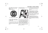
<Remote Control Box Location>
Install the remote control box in the
position where is easy to operate the
remote control lever and switches.
Be sure that there are no obstacles on
the route of the control cable.
The control box position of the R2
type and the R3 type should be
determined in the same manner.
<Remote Control Cable Length>
Measure the distance from the control
box to the outboard motor along the
cable routing.
Recommended cable length is
300 – 450 mm (11.8 – 17.7 in) longer
than the measured distance.
Set the cable along the predetermined
route and be sure that it is long
enough to the route.
Connect the cable to the engine and
be sure it is not kinked, bent sharp,
pulled taut, or interfered while
steering.
Do not bend the remote control
cable as sharp as its route diameter
is 300 mm (11.8 in) or less, or it
affects the service life of the cable
and the remote control lever
operation.
REMOTE CONTROL LEVER
REMOTE
CONTROL BOX
REMOTE
CONTROL
CABLE
Summary of Contents for BFT 115A
Page 2: ...OWNER S MANUAL Original instructions BFT115A 150A ...
Page 120: ...117 17 EC DECLARATION OF CONFORMITY CONTENT OUTLINE ...
Page 121: ...118 EC DECLARATION OF CONFORMITY CONTENT OUTLINE ...
Page 122: ...119 EC DECLARATION OF CONFORMITY CONTENT OUTLINE ...
Page 123: ...120 EC DECLARATION OF CONFORMITY CONTENT OUTLINE ...
Page 124: ...121 EC DECLARATION OF CONFORMITY CONTENT OUTLINE ...
Page 128: ...125 MEMO ...
Page 129: ...OWNER S MANUAL BFT115A 150A ...


