25
CONTROLS AND FEATURES
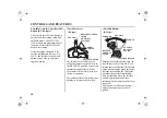
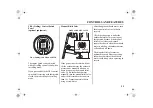
For the sake of the operator’s and the
passenger’s safety, be sure to set the
emergency stop switch clip located at
one end of the emergency stop switch
lanyard with the emergency stop
switch. Attach the other end of the
emergency stop switch lanyard
securely to the operator.
If the emergency stop switch
lanyard is not set, the boat might
run out of control when the
operator, for example, falls
overboard and is not able to
operate the outboard motor.
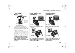
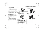
Spare Emergency Stop Switch Clip
A spare emergency stop switch clip is
provided on the remote control box.
(R2, R3 types)
A spare emergency stop switch clip
does not come with R2, R3 type.
A spare emergency stop switch clip
is available from your outboard motor
dealer.
A spare emergency stop switch clip
can be stored in the tool bag (see page
82).
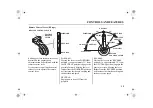
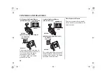
(R1 type)
STOP
STOP
EMERGENCY STOP
SWITCH CLIP
EMERGENCY STOP
SWITCH LANYARD
EMERGENCY
STOP SWITCH
EMERGENCY STOP
SWITCH CLIP
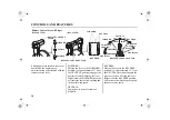
(R2, R3 types)
EMERGENCY STOP SWITCH
EMERGENCY STOP
SWITCH LANYARD
SPARE EMERGENCY
STOP SWITCH CLIP
(R1 type)
Summary of Contents for BFT 115A
Page 2: ...OWNER S MANUAL Original instructions BFT115A 150A ...
Page 120: ...117 17 EC DECLARATION OF CONFORMITY CONTENT OUTLINE ...
Page 121: ...118 EC DECLARATION OF CONFORMITY CONTENT OUTLINE ...
Page 122: ...119 EC DECLARATION OF CONFORMITY CONTENT OUTLINE ...
Page 123: ...120 EC DECLARATION OF CONFORMITY CONTENT OUTLINE ...
Page 124: ...121 EC DECLARATION OF CONFORMITY CONTENT OUTLINE ...
Page 128: ...125 MEMO ...
Page 129: ...OWNER S MANUAL BFT115A 150A ...


