10
LINE OUT H C E
H C
1 2 3
E LINE/MIC IN
LINE
MIC
ON
OFF[PHANTOM]
0dB [PAD]
-20dB
LAN 52V
CTRL OUT
CTRL IN
LINK/ACT
To amplifier, etc.
From microphone or other sound sources
IP-A1AF
Line output terminal
LINE/MIC input terminal
DIP switch
When the connected unit has an unbalanced input, make the connections as follows:
IP-A1AF
Connected unit
H
E
HOT (H)
Cold (C)
Earth (E)
Shield
Shield
DIP switch
1 2 3
LINE
MIC
ON
OFF[PHANTOM]
0dB [PAD]
-20dB
LINE/MIC IN
IP AUDIO INTERFACE IP-A1AF
OUTPUT
VOLUME SIGNAL
SIGNAL
STATUS
SPEAKER
CLASS 2 WIRING
Câblage de classe 2
8-16Ω
Decrease
Increase
LINE/MIC input
volume control
LINE/MIC input signal indicator
IP-A1AF
VOLUME
9.2. Connections to LINE/MIC Input and Line Output Terminals
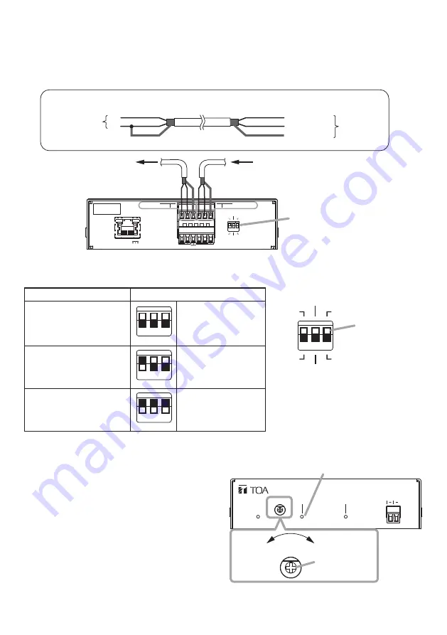
Use the supplied removable terminal plugs (6 pins) for connection. Use a 2-core shielded cable to
connect the audio device.
For connection of the removable terminal plugs, see "Removable Terminal Plug Connections" on
Set the DIP switch according to the audio device to be connected.
[DIP switch settings]
Input device
DIP switch settings
Line level sound source
1 2 3
1: LINE
2: 0 dB [PAD]
3: OFF [PHANTOM]
(Default settings)
Dynamic microphone
1 2 3
1: MIC
2: 0 dB [PAD]
3: OFF [PHANTOM]
Electret condenser
microphone
1 2 3
1: MIC
2: –20 dB [PAD]
3: ON [PHANTOM]
Note
Please change DIP switch settings
while the power is off.
[LINE/MIC input level adjustment]
Set roughly the volume of individual connected
devices by DIP switch. After that, use the
LINE/MIC input volume control for fine volume
adjustments.
Adjust the level so that the LINE/MIC input signal
indicator lights green, not red.
Note
Rotate the input volume control screw using an
appropriate screwdriver. When rotating, do not
press on the screwdriver with too much force, so
as to avoid damage to the adjuster.


