


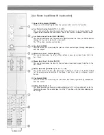


Channel Input Connector [LOW-Z]
The XLR-type input connectors are electronically balanced with a nominal level of –60 dB and an im-
pedance of 600 ohms, and will accept signals from –60 dB to 0 dB. Phantom powering is provided
for use with condenser-type microphones (see PHANTOM), and once again the proper adjustment of
Pad and Trim control [PAD/TRIM] and input fader will insure optimum signal to noise ratio and mini-
mum distortion.
LOW-Z input connector is automatically disconnected when the corresponding HIGH-Z input jack is
used.
Channel Input Jack [HIGH-Z]
This standard 1/4" phone jack is balanced, with a nominal level of –60 dB and an impedance of 10k
ohms, and will accept signal from –60 dB to 0 dB.
Accessory Input Jack [ACCESSORY IN]
This standard 1/4" phone jack is unbalanced, with a nominal level of –10 dB and an impedance of
10k ohms. The Accessory jacks allow signal processing and effect devices to be inserted into the
signal path. The regular signal path is interrupted when a plug is inserted into the Accessory in jack.
Accessory Output Jack [ACCESSORY OUT]
This standard 1/4" phone jack is unbalanced, with a nominal level of –10 dB and an impedance of
1k ohms.
Phantom Power Switch [PHANTOM]
The Phantom power switch on each 4 channels permits the user to supply 24 V DC through the XLR-
type channel input connectors to condenser microphones. If phantom power is not required, the
switch must be in the "off" position.
Aux Return Input Jack [AUX RETURN]
These 1/4" phone jacks are unbalanced, and can be used in conjunction with the Aux send jack to
connect an outboard effect device (ie., Delay or Reverb) to this mixing console. The Aux return jack
should be connected to the output of the effect. Nominal input level is +4 dB with an impedance of
10k ohms.
Note:
Connect to both "AUX RETURN L-R" when an outboard effect device has a Stereo output from
two unbalanced 1/4" phone plugs. The outboard effect device's stereo Left and Right chan-
nels are then assigned to the Group 1 and 2, or Group 3 and 4, or Stereo L and R busses,
respectively.
Connect to "AUX RETURN R/MONO" when the outboard effect device has a mono-output, the
mono signal will automatically be assigned to both Group 1 and 2, or Group 3 and 4, or
Stereo L and R busses.
– 9 –
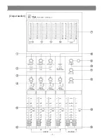
Panel facilities (Rear panel)
Summary of Contents for CX-124
Page 7: ...Output section GROUP STEREO 7...
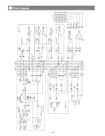
Page 14: ...14 Block diagram...
Page 15: ...15 Level diagram...