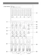


[Channel input section]
Pad Switch [PAD]
Pad switch inserts a –20 dB pad ahead of the head amplifier. Adjust the PAD switch,
depending on the output level of microphones or associated equipment.
Signal/Peak LED Indicator [SIG/PEAK]
The dual color LED indicator lights green when the pre-EQ signal level reaches 20 dB
before from nominal level, and turns red when the signal level reaches 6 dB below clip-
ping, giving a visual reference for optimum setting of the trim control.
Input Trim Control [TRIM]
The Trim control adjusts the gain of the preamplifier stage of the associated channel,
providing 40 dB of gain control. The Trim control and Pad switch of each channel
should be properly adjusted so that the peak LED is just being to turn red from green
or only flash red occasionally. This will ensure lowest distortion level and optimum sig-
nal to noise ratio.
High Equalizer Control [HIGH]
The High EQ control alters the high frequency response of the input channel, providing
±15 dB at continuously variable active shelving equalization. The "0" detent position
provides flat audio response.
Mid Equalizer Control [MID]/Mid Equalizer Center Frequency Control [MID FREQ]
The Mid EQ frequency control alters the center frequency of the Mid EQ control in the
range from 300 Hz to 4 kHz.
The Mid EQ control alters the mid frequency response of the input channel, providing
±15 dB at the center frequency of peaking equalization. The "0" detent position pro-
vides flat audio response.
Low Equalizer Control [LOW]
The Low EQ control provides ±15 dB at continuously variable active shelving equaliza-
tion. The "0" detent position provides flat audio response.
– 4 –
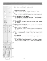
Panel facilities (Front panel)
Summary of Contents for CX-124
Page 7: ...Output section GROUP STEREO 7...
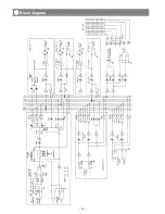
Page 14: ...14 Block diagram...
Page 15: ...15 Level diagram...