Toa CX-124 Operating Instructions Manual Download Page 10

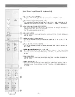
Stereo  Input  Jack [STEREO IN]

These RCA pin jacks are unbalanced, with a nominal of –10 dB and an impedance of 10k ohms.
The Stereo input jacks  should be connected to an outboard stereo unit (ie., Tape deck, CD player).

Cue Output Jack [CUE OUT]

These 1/4" phone jacks are unbalanced, and provide the same signal as the Headphone  output, and
are used for monitoring the signals of the Cue busses through  monitor speakers. This jack has a

nominal  output level of +4 dB and an impedance of 1k ohms.

Aux Send Jack [AUX SEND]

These 1/4" phone  jacks can be used in conjunction with the Aux return jack to connect an outboard
effects  device  (ie.,  Delay or Reverb) to this mixing console. The Aux send  jack  should be connected
to the input of the effect.  Nominal  output level is +4 dB with an impedance of 1k ohms.

Recording Output Jack [REC OUT]

These RCA pin jacks are unbalanced, with a nominal  output level of –10 dB and an impedance of 1k
ohms. These jacks provide pre-Stereo fader signals for connection to tape recorders.

Group Output Connector [GROUP  OUT]

The electronically balanced XLR connectors  have a nominal output level of +4 dB and an impedance
of 600 ohms.

Stereo Output Connector [STEREO OUT]

The electronically balanced XLR connectors have a nominal output level of +4 dB and an impedance
of 600 ohms.

Sum Output Connector [SUM OUT]

The electronically balanced XLR connector has a nominal output level of +4 dB and an impedance
of 600 ohms.

Power Switch [POWER]

This switch provides AC power to the mixer. Power should only be applied after all audio connections

have been completed. The power LED indicator lights when the switch is "on".

AC Power Cord

– 10 –

Summary of Contents for CX-124

Page 1: ...e follow the instructions in this manual to obtain the optimum results from these units We also recommend you to keep this manual handy for future re ference TOACorporation KOBE JAPAN Operating Instru...

Page 2: ...ition to prevent damage to speakers etc XLR type audio connectors are factory wired as follows Pin 1 ground shield pin 2 cold low minus and pin 3 hot high plus Where microphone cables connected to uni...

Page 3: ...to meet a wide range of requirements The high performance and modular con struction assures reliability easy maintenance and service ability 2 channel Stereo input is provided in addition to the chann...

Page 4: ...rn red from green or only flash red occasionally This will ensure lowest distortion level and optimum sig nal to noise ratio High Equalizer Control HIGH The High EQ control alters the high frequency r...

Page 5: ...witch for localization of sound image Channel Switch CH This switch connects or disconnects the input signal to the mixing busses The LED indicator lights orange when the channel on off switch is on A...

Page 6: ...Headphones and Cue output Stereo Input Aux 1 Control AUX 1 This control determines the level of the pre fader stereo input signal to be fed to the Aux 1 buss Stereo Input Aux 2 Control AUX 2 This con...

Page 7: ...Output section GROUP STEREO 7...

Page 8: ...D bargraph meter indicates the Group output 1 2 3 4 Aux Send 1 2 3 Sum output or Stereo output L R The meter indicates 0 dB with 4 dB nominal output Meter Select Switch METER The meter indicates the G...

Page 9: ...k Accessory Output Jack ACCESSORY OUT This standard 1 4 phone jack is unbalanced with a nominal level of 10 dB and an impedance of 1k ohms Phantom Power Switch PHANTOM The Phantom power switch on each...

Page 10: ...f the effect Nominal output level is 4 dB with an impedance of 1k ohms Recording Output Jack REC OUT These RCA pin jacks are unbalanced with a nominal output level of 10 dB and an impedance of 1k ohms...

Page 11: ...Tapedeck for play back Effector etc Microphone Power amplifier Main speaker Tapedeck for recording Monitor speaker Power amplifier 11 Connection diagram for CX 124 and CX 164...

Page 12: ...rear panel into both metals on the left and right side panels Take out connector from part Fix the input transformer using the attached three screws as shown in the figure Insert connector into part I...

Page 13: ...Connector XLR 3 31 or equivalent Balanced Phone Jack Balanced Phone Jack Unbalanced Pin Jack Phone Jack Unbalanced Output GROUP OUT 1 4 STEREO OUT L R SUM OUT AUX SEND 1 2 3 ACCESSORY OUT 1 12 16 CUE...

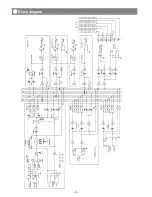
Page 14: ...14 Block diagram...

Page 15: ...15 Level diagram...

Page 16: ...Hz 15 dB Shelving MID 300 Hz 4 kHz variable 15 dB Peaking HIGH 20 kHz 15 dB Shelving Peak Indicator LED turns on when the pre fader and post EQ signal reaches 6dB before clip Phantom Power 24V DC AC L...

Reviews: