


Medium & Heavy Payload Series-Hardware Installation Manual TM12/14 Series Hardware Version: 3.2
Document Version: 1.01
75
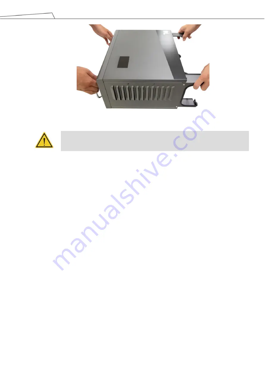
Figure 74: Moving the Control Box (2/2)
WARNING:
At this stage, do not connect the power cable of the control box to any electrical outlet, or it
may cause equipment damage.
6.4.2
Verification Before Removal of the Robot Arm
The TM Robot arm cannot stand independently after being removed from the carton. Prepare four screws
(M10 *4) that used to attach the robot to the base near the robot base in advance. If the base is designed
with corresponding pinholes, mount them to the base.
6.4.3
Removal of the Robot Arm and Tightening
At least two people should remove the robot arm from the carton. For the correct holding positions, refer
to the figure below. Place the robot on the mounting base. If it is designed with connection pins, align the
pinholes of the robot base module. Tighten two locking screws with metal washers for the robot base that
are diagonally across from each other, and then tighten the other two locking screws.
Follow the tightening torque recommended in 4.2.1.6 Robot Arm Installation


