


Medium & Heavy Payload Series-Hardware Installation Manual TM12/14 Series Hardware Version: 3.2
Document Version: 1.01
48
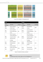
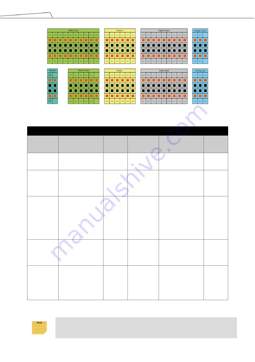
Figure 38: Control Box I/O Configuration (2/2)
Input
Output
Safety
Connector
Definition
SF Input
Safety
Connector
Definition
SF Output
SI0-1
SI0-2
User Connected
ESTOP Input
SF1
SO0-1
SO0-2
Robot ESTOP
Output
SF10
SI1-1
SI1-2
User Connected
External Safeguard
Input
SF3
SO1-1
SO1-2
User Connected
External Safeguard
Output
SF11
SI2-1
SI2-2
User Connected
External Safeguard
Input for Human–
Machine Safety
Settings
SF9
SO2-1
SO2-2
User Connected
External Safeguard
Output for Human–
Machine Safety
Settings
SF12
SI3-1
SI3-2
User Connected
Enabling Device
Input
SF15
SO3-1
SO3-2
Robot Internal
Protective Stop
Output
SF13
SI4-1
SI4-2
User Connected
ESTOP Input without
Robot ESTOP
Output
SF16
SO4-1
SO4-2
Robot Encoder
Standstill Output
SF14
Table 10: Definitions of Safety Connectors
NOTE:
For details about safety functions, please refer to the
Safety Manual
.


