background image

TM INDUCTION HEATING

 10

ST PRO  2.3   |

INSTALLATION

3

SCOPE OF 
DELIVERY

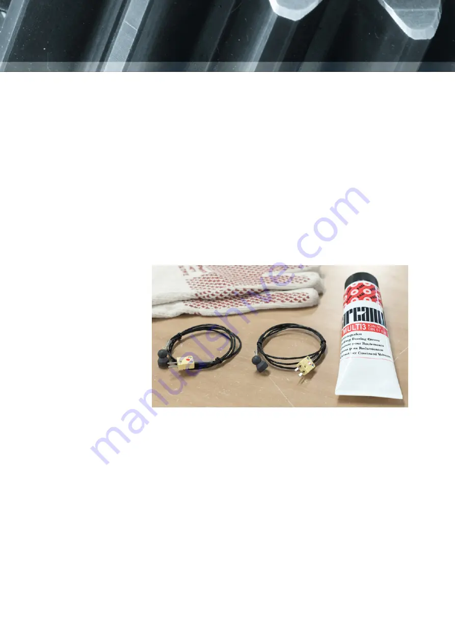
Contents of the box

1. 

SURETHERM PRO  1X / 3X / 6X

2.  Temperature probes

3.  Heat-resistant gloves

4.  User Manual

5.  Quickstart guide

Note

The yokes for 

SURETHERM PRO

 induction heaters

 are all optional. The 

SURETHERM  PRO

 induction heaters

 are delivered with two magnetic 

temperature probes included. The heat-resistant gloves may differ from 

the picture above.

Follow the instructions specific for this heater on the supplied Quickstart 

guide. If the Quickstart guide is not included in this box, please contact 

your distributor or TM Induction Heating directly. The induction heater 

must always be transported in the original box, thus also on return to the 

manufacturer/distributor.

UNBOXING

Summary of Contents for Suretherm Pro 1X

Page 1: ...ISO 9001 2015 ID 9000001589 www tuv com User Manual ...

Page 2: ...ducts are subject to continuous improvement we reserve the right to make changes WEB MAIL TEL FAX ADDRESS TM Induction Heating Nobelstraat 14 3846 CG Harderwijk The Netherlands T M Techniek BV BTW NL800643136B01 KvK 08054481 tminductionheating com info tminductionheating com 31 0 341 434454 31 0 341 434464 ISO 9001 2015 ID 9000001589 www tuv com ...

Page 3: ...WORKPIECE 12 Choosing the yoke 13 Manual Power Adjustment 13 Positioning the magnetic temperature probe s 14 OPERATION 15 Temperature Mode using one sensor 16 Ramp Mode 17 Temperature Mode using two sensors 18 Time Mode 19 User menu 20 MAINTENANCE 21 MALFUNCTION 22 Adjusting the yoke 22 Errors 23 SPECIFICATIONS 24 Technical data 25 Extra information 26 Electrical drawings 27 STATEMENT OF CONFORMIT...

Page 4: ...TM INDUCTION HEATING 4 ST PRO 2 3 ...

Page 5: ...check the heating cycle When heating an object using Time Mode the heating cycle must be checked using an external temperature meter CAUTION Bearings generally should only be heated to a maximum temperature of 120ºC 248ºF Do not use induction heaters for bearings or workpieces with dimensions outside the ranges specified in this manual Do not switch off the heater with the main switch while heatin...

Page 6: ... with the safety precautions In order to prevent danger or damage to the induction heater or workpiece follow these guidelines All repairs must be carried out by an official TM Induction Heating distributor Use original spare parts only Protect the heater from water or very high humidity Protect the heater core and yokes against corrosion damage and deformation Only preheat bearings to max 120 C 2...

Page 7: ...ice Other sensitive equipment such as wrist watches magnetic carriers electronic circuits etc 3 might also be affected The safety distance is 0 5 meters 19 Use protective gloves as protection against burns to hands The gloves delivered are suitable for use up to temperatures of 150 C 302 F Hot surface avoid contact 6 Do not operate an induction heater in areas where there is risk of explosion Wear...

Page 8: ...g in the proximity of the magnetic field Extremely high currents can flow through the cable causing it to heat up quickly resulting in a risk of burning Do not place any metal objects near the yokes and poles Place heater on a stable horizontal surface Keep a minimum distance of 1 metre 38 to surrounding objects Use only in well ventilated areas Do not heat objects containing oil grease or similar...

Page 9: ...nsity in microTesla µT These measurements can be used as a guide conforming to local regulations regarding the maximum time exposure to magnetic fields Different configurations may give different values It is impossible to provide values for all combinations as the variety of bearing types in combination with the different yokes is large Total 50Hz RMS field for magnetic measurement results Max ma...

Page 10: ...RM PRO induction heaters are delivered with two magnetic temperature probes included The heat resistant gloves may differ from the picture above Follow the instructions specific for this heater on the supplied Quickstart guide If the Quickstart guide is not included in this box please contact your distributor or TM Induction Heating directly The induction heater must always be transported in the o...

Page 11: ...SS Ensure that supply voltage and current meet the specifications These can be found on the type plate at the back of the induction heater Not all of our induction heaters are provided with a plug mainly because there are a large number of plug types A suitable plug must be affixed by a qualified electrician Voltages may differ for customized heaters Phase X L1 Phase Y L2 Ground Voltage 460 575V G...

Page 12: ... weight as shown in chapter 8 WORKPIECE DIMENSIONS Exceeding these limits may result in catastrophic equipment failure and may also lead to personal injury Ensure there is no contact between the mains cable and the workpiece Damage to the cable may result in electrocution Never support components with a metal cable and avoid cables hanging in the proximity of the magnetic field Extremely high curr...

Page 13: ...t yokes carefully Falling bumping can damage the yoke and or cause personal injury Store the yoke safely immediately after use CHOOSING THE YOKE When using RAMP MODE or TEMP TWO SENSOR MODE the actual effective power will constantly change during the heating cycle This is done fullyautomatic WhenusingTIMEMODEorTEMP ONESENSORMODEthe standard effective power is 100 Turning the power down is needed w...

Page 14: ...0 C 464 F The connection between magnet and probe will break above the maximum temperature If this occurs when operating in Temperature Mode the heater will turn itself off as the probe will fail to register any increase in the temperature over a set period of time Probes for higher temperatures are optional Connect the probe by inserting the plug into the socket at the front of the heater with th...

Page 15: ...n a second sensor is inserted The start stop button is used for starting heating cycles in one of the modes or to stop a heating cycle at any time When a heating cycle is complete or stopped prematurely the program will return to the main screen of the heating mode A graph can be requested with the graph button Every mode has three stages 1 Preparation The user can change the temperature and or ti...

Page 16: ...to start the heating process press the start button on the remote 1 PREPARATION 2 HEATING PROCESS 3 COMPLETION Press or to change the temperature max 240 C To change the temperature press to change the max power output press Otherwise proceed to step 2 Press when the temperature is set TEMPERATURE MODE ONE SENSOR Press or to change the max power output Press when the max power output is set When u...

Page 17: ...g cycle The induction heater will now demagnetize Hereafter it will return to the first screen Alternatively to start the heating process press the start button on the remote 1 PREPARATION 2 HEATING PROCESS 3 COMPLETION Press or to change the temperature max 240 C Press or to change the time To change the temperature press to change the heating time press Otherwise proceed to step 2 Press when the...

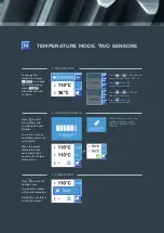
Page 18: ...ater will now demagnetize Hereafter it will return to the first screen Alternatively to start the heating process press the start button on the remote 1 PREPARATION 2 HEATING PROCESS 3 COMPLETION Press or to change the temperature max 240 C Press or to change the Δ temperature To change the temperature press to change the Δ temperature press Otherwise proceed to step 2 Press when the temperature i...

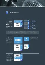
Page 19: ...ss press the start button on the remote TIME MODE 1 PREPARATION 2 HEATING PROCESS 3 COMPLETION Press or to change the time max 99 59 To change the heating time press To change the max power output press Otherwise proceed to step 2 Press when the time is set Press or to change the max power output Press when the max power output is set When using smaller yoke sizes on a SURETHERM PRO heater make su...

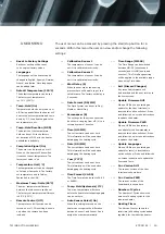
Page 20: ...Update Firmware PWR When a USB drive containing an update for the Powerboard is inserted this option will show Press and follow the on screen instructions to update the heater Update Languages When a USB drive containing an update for texts is inserted this option will show Press and follow the on screen instructions to update the Fonts and Texts Cur Version GUI The current version of the User Int...

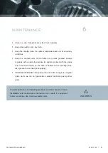
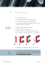
Page 21: ...rease for optimal contact with the yokes and to avoid corrosion in the case of heaters with a pivoting yoke also grease the vertical pin regularly CRITICAL SPARE PART Magnetic probe 0110010 Always use original spare parts we can not guarantee a proper functioning using other parts MAINTENANCE 6 Proper maintenance and handling practices are critical Failure to follow installation and maintenance in...

Page 22: ...on Are the contact surfaces clean and greased sufficiently Are the yokes 100 in contact with the surface If this is not the case adjust the yoke with instructions below 1 Check if the machine milled surface is smooth 2 Place yoke or pivoting yoke on the heater 3 Unscrew the screws in the yoke and pivoting point a quarter turn 4 Turn on the heater and the yoke will set itself or use a nylon hammer ...

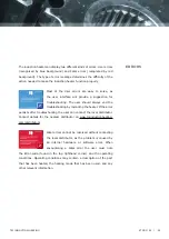
Page 23: ...ys end the troubleshooting by restarting the heater If the error persists after troubleshooting the user can contact the local distributor Contact details for the nearest distributor on www tminductionheating com distributors Fatal errors cannot be resolved without contacting the local distributor as the problem is caused by an internal hardware or software error When encountering a Fatal error th...

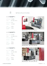
Page 24: ...voting execution Power rating 12 8 kVA Voltage 400 480 575 V Current max 32 A Frequency 50 60Hz Power rating 25 2 kVA Voltage 400 480 575 V Current max 63 A Frequency 50 60Hz Power rating 40 kVA Voltage 400 480 575 V Current max 100 A Frequency 50 60Hz Weight 157 kg Max weight workpiece 400 kg Weight 280 kg Max weight workpiece 800 kg Weight 650 kg Max weight workpiece 1600 kg ...

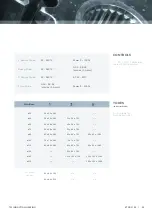
Page 25: ...1080 ø100 70 x 70 x 490 P 70 x 70 x 750 n a ø115 80 x 80 x 490 P 80 x 80 x 750 80 x 80 x 1080 ø130 n a 90 x 90 x 750 n a ø145 n a 100 x 100 x 750 100 x 100 x 1080 ø215 n a n a 150 x 150 x 1080 YOKES IN MILLIMETERS P Available for Pivoting execution Min Bore Ext yokes lxwxh 80 x 80 x 150 P n a n a 80 x 80 x 200 P n a n a 1 Sensor Mode 20 240 C Power 5 100 Ramp Mode 20 240 C 0 00 99 59 mm ss hh mm 2...

Page 26: ...emperature time and power 2 Sensor Mode Set actual temperature ΔT time and power Time Mode Set actual time External interface USB 2 0 Port Sound signal Buzzer Demagnetizing 2A cm Temperature hold Yes Thermal safety guard coil Yes Magnetic probe 2 sensors ADDITIONAL INFORMATION Languages English Spanish German French Italian Warranty 24 months Extended Warranty 12 months ...

Page 27: ...TM INDUCTION HEATING 27 ST PRO 2 3 ELECTRICAL DRAWING Electrical drawing SURETHERM PRO 1X Start Stop ...

Page 28: ...TM INDUCTION HEATING 28 ST PRO 2 3 ELECTRICAL DRAWING Electrical drawing SURETHERM PRO 3X Start Stop ...

Page 29: ...TM INDUCTION HEATING 29 ST PRO 2 3 ELECTRICAL DRAWING Electrical drawing SURETHERM PRO 6X Start Stop ...

Page 30: ...TM INDUCTION HEATING 30 ST PRO 2 3 ...

Page 31: ...lity of SURETHERM induction heaters This declaration indicates that the product meets the requirements of the directives which are applicable The SURETHERM induction heaters are manufactured in accordance with European regulations CE compliant As CE marking is a mandatory conformity marking for products sold within the European Economic Area these declarations do not cover any regions outside Euro...

Page 32: ...s defined by MACHINE DIRECTIVE 2006 42 EC LOW VOLTAGE DIRECTIVE 2014 35 EU and EMC DIRECTIVE 2014 30 EU In conjunction with the following harmonized standards and where appropriate other technical standards and specifications Risk Assessment EN ISO 12100 2010 Design Manufacture EN IEC 61000 4 6 2007 A1 2011 EN IEC 60204 1 2006 C11 2010 NEN 3140 A1 2015 Name Mr E van Dijk Function General Manager S...

Page 33: ...s defined by MACHINE DIRECTIVE 2006 42 EC LOW VOLTAGE DIRECTIVE 2014 35 EU and EMC DIRECTIVE 2014 30 EU In conjunction with the following harmonized standards and where appropriate other technical standards and specifications Risk Assessment EN ISO 12100 2010 Design Manufacture EN IEC 61000 4 6 2007 A1 2011 EN IEC 60204 1 2006 C11 2010 NEN 3140 A1 2015 Name Mr E van Dijk Function General Manager S...

Page 34: ...s defined by MACHINE DIRECTIVE 2006 42 EC LOW VOLTAGE DIRECTIVE 2014 35 EU and EMC DIRECTIVE 2014 30 EU In conjunction with the following harmonized standards and where appropriate other technical standards and specifications Risk Assessment EN ISO 12100 2010 Design Manufacture EN IEC 61000 4 6 2007 A1 2011 EN IEC 60204 1 2006 C11 2010 NEN 3140 A1 2015 Name Mr E van Dijk Function General Manager S...

Page 35: ...user manual SURETHERM PRO version 2 3 2020 ...

Page 36: ......

Reviews: