( )
( )
( )
(1)
(1)
( )
36
60
24
26
26
27
1. Is the pipe diameter suitable?
2. Has the trap been installed within the allowable inclination and with the arrow on the body
pointing in the direction of flow?
3. Has sufficient space been secured for maintenance?
4. Have maintenance valves been installed at inlet and outlet? If the outlet is subject to back
pressure, has a check valve been installed?
5. Is the inlet pipe as short as possible, with as few bends as possible, and installed so that the
condensate will flow naturally down into the trap?
6. Has the piping work been done with the proper methods, as shown in the table on page 8?
Check to make sure that the pipes connected to the trap have been installed properly.
Operational inspections should be performed at least twice per year, or as called for by trap
operating conditions. Steam trap failure may result in temperature drop in the equipment, poor
product quality or losses due to steam leakage.
6. Inspection and Maintenance
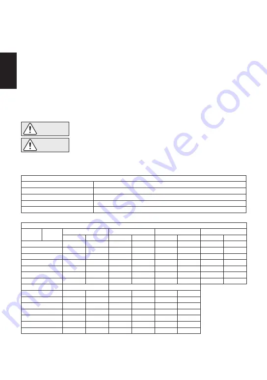
WARNING
NEVER apply direct heat to the float. The float may explode due to
increased internal pressure, causing accidents leading to serious injury or
property and equipment damage.
• Installation, inspection, maintenance, repairs, disassembly, adjustment
and valve opening/closing should be carried out only by trained
maintenance personnel.
• Before attempting to open the trap, close the inlet and outlet isolation valves and wait until the
trap has cooled completely. Failure to do so may result in burns.
• Be sure to use the proper components and NEVER attempt to modify the product.
CAUTION
Body, Cover (s)
Gaskets
Screen
Float
Valve Seat
Check inside for damage, dirt, grease, oil film, rust or scale
Check for warping or damage
Check for clogging, corrosion or damage
Check for deformation, damage, oil film or water inside
Check for rust, scale, oil film, wear or damage
Parts Inspection Procedure
Tightening Torque and Distance Across Flats
Parts &
Number Model
Cover Nut 12
Orifice 4
Orifice Plug 6
Outlet Cover Nut 22
Drain Plug 19*
Orifice Locknut 20
Cover Plug 14
Model
Cover Nut 12
Orifice 4
Orifice Plug 6
Outlet Cover Nut 22
Drain Plug 19*
Cover Plug 14
Plug (Interior) 25
1 N·m 10 kg·cm
JH5RL-P
160
140
180
35
100
(115)
(100)
(130)
(26)
(73)
22
17
38
21
26
( )
( )
( )
( )
(1)
* Option for JH5RL-P, JH5RH-P
If drawings or other special documentation were supplied for the product, any torque given there
takes precedence over values shown here.
/
32
21
/
16
13
/
8
7
/
2
1
1
JH5RH-P
170
140
180
35
100
(125)
(100)
(130)
(26)
(73)
24
17
38
21
26
( )
( )
( )
( )
(1)
mm (in)
N·m(lbf·ft)
/
32
21
/
32
31
/
16
13
/
16
15
/
2
1
1
JH7RM-P
200
280
420
100
100
(150)
(205)
(310)
(73)
(73)
24
26
50
26
26
( )
(1)
( )
(1)
(1)
mm (in)
N·m(lbf·ft)
/
16
15
JH7RH-P
700
200
250
100
(510)
(150)
(185)
(73)
46
30
32
26
( )
( )
( )
(1)
mm (in)
N·m(lbf·ft)
/
4
1
1
/
16
13
1
/
16
3
1
JH7.2R-P
180
350
700
100
100
(130)
(260)
(510)
(73)
(73)
24
38
46
26
26
( )
( )
( )
(1)
(1)
/
16
15
/
2
1
1
/
8
3
2
JH7.5R-P
200
600
800
100
100
150
(150)
(440)
(590)
(73)
(73)
(110)
30
46
46
26
26
27
( )
( )
( )
(1)
(1)
( )
JH8R-P
450
1000
160
100
100
150
(330)
(730)
(115)
(73)
(73)
(110)
/
16
13
1
/
16
13
1
/
16
13
1
/
32
13
1
/
16
1
1
/
16
3
1
/
16
15
/
16
1
1
N·m(lbf·ft) mm (in)
1
̶ 9 ̶
English


