172-65116M-02 (CP-N) 16 Jun 2011
15
a. Adjust
V
3
so that P
1
comes to the designed value. To lower P
1
, turn the
pressure adjusting knob of V
3
counter-clockwise. To raise P
1
, turn the knob
clockwise.
b. Adjust
P
2
to keep following relation;
Pump Head[mH]
×
Specific Gravity[kg/m
3
]
P2[MPaG] > P1[MPaG] +
100
To lower P
2
, turn the pressure adjusting knob of V
9
counter-clockwise. To
raise P
2
, turn the knob clockwise.
c. Adjust the pressure switch setting (P
2
S) as follows.
P
1
+ P
2
P
2
S =
2
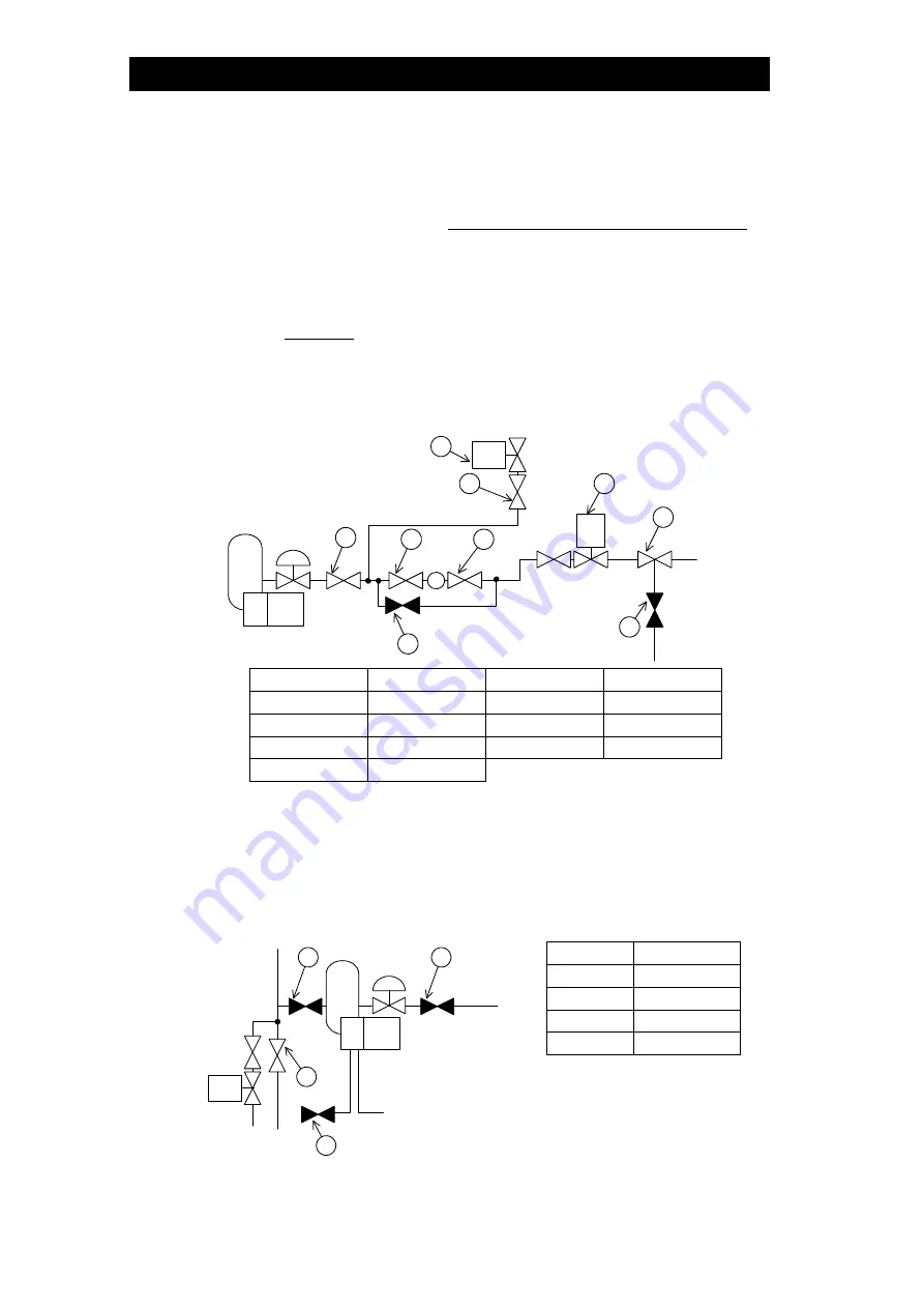
(8) Feed the condensate into the boiler automatically. To do this, put the select
switch for feed water control to the “automatic” position.
M B
3
M B m
V
O
V n
V
10
V
12
V
13
V
11
V
14
FM
Symbol Operation Symbol Operation
V
11
Close V
n
Close
V
12
Open V
o
Open
V
13
Open V
10
Open
V
14
Open
(9) Verify the conditions of the entire system and the recovery conditions.
(10) Stoppage
a. Put the select switch for pump operation to the “OFF” position.
b. Close
V
10
.
c. Turn off the power switch on the control panel.
d. Open
V
5
and close V
7
.
e. Close
V
8
to stop cooling water (about 10 minutes after the pump stops).
V
5
V
8
V
10
V
7
Symbol Operation
V
5
Open
V
7
Close
V
8
Close
V
10
Close


