background image

6

2.2.  Hardware assembly


—  Mount the UR robot to the required position. For SAN2 application the orientation of the robot may be arbitrary 

regarding your particular setup. Connect the robot and UR Control box. During this step, please follow Universal Robots 
instructions delivered together with the robot


—  To connect and assemble the SAN2 system, please follow the document 

Equipment Installation

 for SAN 2.


The rivet charger has to be mounted in the fixed position


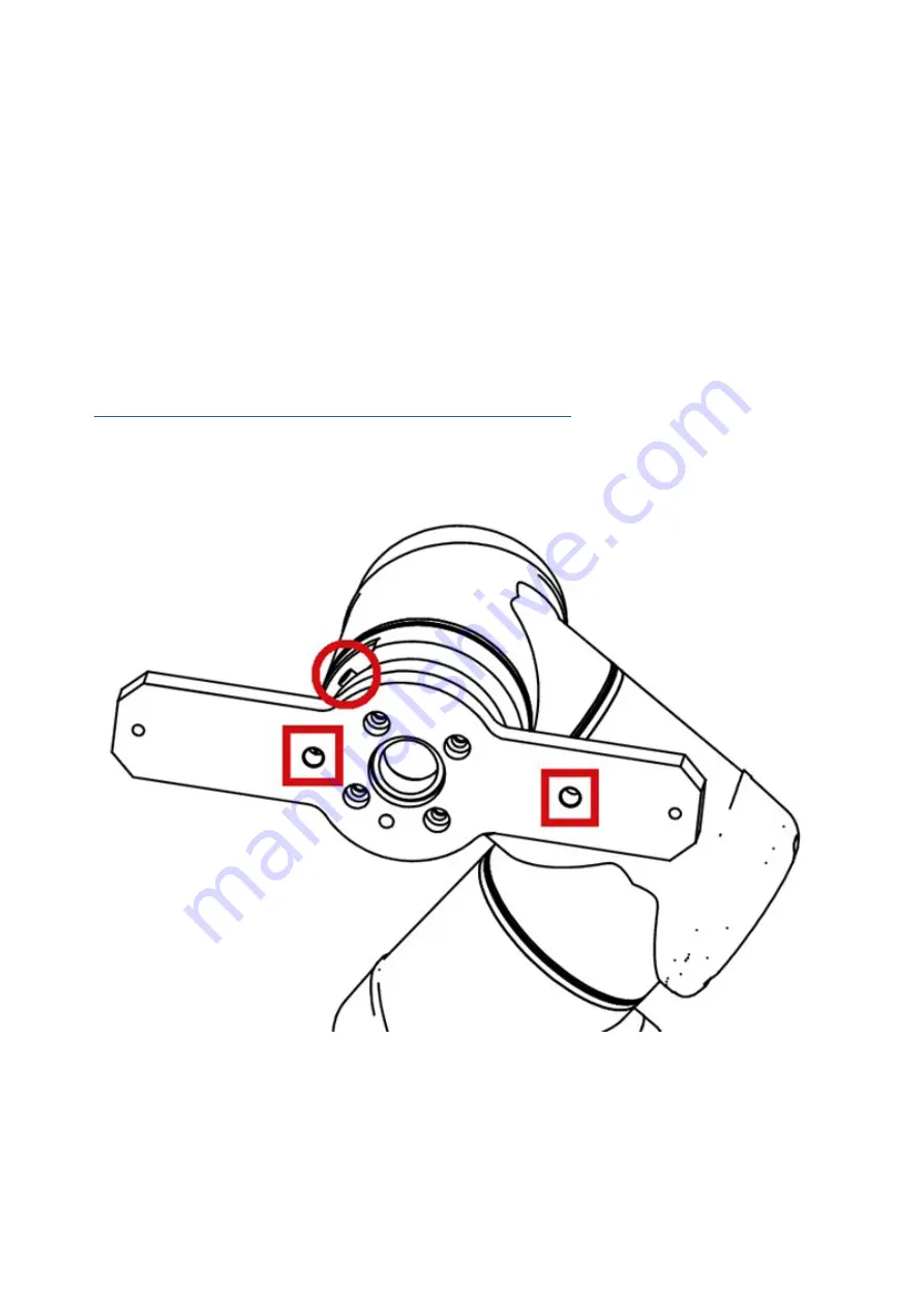
— The riveting head has to be mounted on the robot arm. The mounting plate between the robot TCP and riveting

    head is provided as a special accessory. When mounting the flange if possible, please follow the orientation

    showed in Figure 2. This orientation is considered when setting the TCP/Tool coordinates and orientation. In case
    this orientation does not suit your application (e.g. robot violates its working envelope), different orientation is
    possible. However, the TCP/Tool orientation has to be setup accordingly


— Note that if the technical support has been requested during the order, our team will help you with assembly 

    and first startup


— Connect the SANK2 control unit and UR Control box with the Ethernet cable


—  Install the SAN2 URCap. For this step, you will need a USB storage device. Download the URCap available at  

https://www.titgemeyer.com/en/tools-automation/service/download-center/


and save it to a USB storage device.  

Insert the USB storage into the robot panel and install the URCap from Settings – System - URCaps menu. Press the  

+ button and navigate to the URCap file on your USB storage device. After the installation the robot has to be restarted

Figure 2 Standard orientation of the flange mounted on the robot arm

All t

echnic

al specific

ations c

ont

ained in this br

ochur

e ar

e appr

o

ximat

e and no g

uar

ant

ee is giv

en as t

o their ac

cur

acy

. De

signs ar

e subjec

t t

o chang

e.

Titgemeyer / 10273EN1120 / 1

Equipment Installation

Summary of Contents for SAN2URCap

Page 1: ...Axles Subline Equipment Installation Implementation manual for SAN2URCap Riveting automation ...

Page 2: ... binding if so expressly agreed Moreover the user is obliged at all times to check each individual use and decide whether the components that we supply can be used as needed We accept liability in the case of wilful intent gross negligence and infringement of cardi nal contractual duties as well as for errors in respect of express or implied representations Notwithstanding this any claims for comp...

Page 3: ...heir accuracy Designs are subject to change Titgemeyer 10273EN1120 1 Page 1 Introduction 4 2 Installation 4 2 1 System requirements 4 2 2 Hardware assembly 6 2 3 Software setup 7 3 Programming the robot 10 3 1 Charging Node 10 3 2 Riveting Node 12 4 Example UR robot program 15 Content Equipment Installation ...

Page 4: ...tallation of the URCap to creating simple example program together with UR robot 1 Introduction 2 1 System requirements The URCap is meant for the following SAN2 setup the setup overview is available in Figure 1 Riveting head mounted on the robot Charger mounted on the fixed point or on the linear motion Vibration bowl may contain the transport booster SANK2 control unit UR robot minimum requireme...

Page 5: ... solid black hydraulics solid gray electronic connection bold gray line rivet transport All technical specifications contained in this brochure are approximate and no guarantee is given as to their accuracy Designs are subject to change Titgemeyer 10273EN1120 1 Equipment Installation ...

Page 6: ...g robot violates its working envelope different orientation is possible However the TCP Tool orientation has to be setup accordingly Note that if the technical support has been requested during the order our team will help you with assembly and first startup Connect the SANK2 control unit and UR Control box with the Ethernet cable Install the SAN2 URCap For this step you will need a USB storage de...

Page 7: ... to be entered Recommended way to compute them is to use the Wizard In any case the proper Payload of 5 55 kg has to be filled in Also the center of gravity coordinates must be entered Otherwise the robot may encounter unexpected protective stop and also its hardware may be damaged by calculating with improper weights and forces This has to be fulfilled even if a new tool is not created and any po...

Page 8: ...the duty a robot restart may be required to contrinue Inputs update frequency Hz Modbus messages rate This rate determines how often per second the robot asks SAN2 for input states Possible values are 1 125 Reasonable values are however between 10 and 25 These values provide fast performance and do not overload the communication channels Timeout of ready s When the SAN2 is switched to the AUTO mod...

Page 9: ...p SAN2 has not been enabled All technical specifications contained in this brochure are approximate and no guarantee is given as to their accuracy Designs are subject to change Titgemeyer 10273EN1120 1 The SAN system Modules for standard rivet nuts ...

Page 10: ...s of the charger ejector Also the distance of the riveting head from the charger has to be adjusted according to the utilized rivet height of the rivet head 3 to 5 mm from the ejected ejector When the riveting position is reached charge rivet can be called Further information about the charging can be found in document Equipment Installation In case the rivet mandrels are bended and cause problems...

Page 11: ...gram node All technical specifications contained in this brochure are approximate and no guarantee is given as to their accuracy Designs are subject to change Titgemeyer 10273EN1120 1 The SAN system Modules for standard rivet nuts ...

Page 12: ...sonable value is between 5 and 20 Select parameter set Specified parameter set for the particular riveting Up to 4 sets can be configured and used for e g different material thickness The parameter set can be configured in SanAssist application supplied together with the SAN2 system In case the evaluation module of the SAN system is disabled please select arbitrary parameter set other than None th...

Page 13: ...Rivet node with NOK result active All technical specifications contained in this brochure are approximate and no guarantee is given as to their accuracy Designs are subject to change Titgemeyer 10273EN1120 1 The SAN system Modules for standard rivet nuts ...

Page 14: ...10 Further use of the provided global variable All technical specifications contained in this brochure are approximate and no guarantee is given as to their accuracy Designs are subject to change Titgemeyer 10273EN1120 1 The SAN system Universal modules ...

Page 15: ...d MoveJ move to the riveting position Rivet set the rivet to the product Do not forget to setup a proper Out of rivet position at least 1 cm above the riveted material If condition check the result of the riveting If NOK pause the process and inform the operator Popup subnode information about NOK riveting result Go to start All technical specifications contained in this brochure are approximate a...

Page 16: ...Titgemeyer Tools Automation spol s r o U Vodárny 1506 39701 Pisek CZ T 420 382 206 711 E info rivetec cz W titgemeyer com ...

Reviews: