background image

2


EN

IMPORTANT SAFETY INFORMATION 

Read all safety information before operating the equipment.  

Save these instructions.
To reduce the risks of fire or explosion, electrical shock and the 

injury to persons, read and understand all instructions included 

in this manual. Be familiar with the controls and proper usage 

of the equipment.

EXPLANATION OF SYMBOLS

This symbol indicates a potential hazard 

that may cause serious injury or loss of life. 

Important safety information will follow.

Attention

This symbol indicates a potential hazard 

to you or to the equipment.  Important 

information that tells how to prevent 

damage to the equipment or how to avoid 

causes of minor injuries will follow.

Danger of skin injection

Danger of fire from solvent and paint fumes

Danger of explosion from solvent, paint 

fumes and incompatible materials

Danger of injury from inhalation of harmful 

vapors

Electric shock hazard

i

Notes give important information which 

should be given special attention.

GROUNDING INSTRUCTIONS

This product must be grounded. In the event of an electrical 

short circuit, grounding reduces the risk of electric shock by 

providing an escape wire for the electric current. This product 

is equipped with a cord having a grounding wire with an 

appropriate grounding plug. The plug must be plugged into 

an outlet that is properly installed and grounded in accordance 

with all local codes and ordinances.

WARNING - Improper installation of the 

grounding plug can result in a risk of electric 

shock.

If repair or replacement of the cord or plug is necessary, do not 

connect the green grounding wire to either flat blade terminal. 

The wire with insulation having a green outer surface with 

or without yellow stripes is the grounding wire and must be 

connected to the grounding pin.

Check with a qualified electrician or serviceman if the grounding 

instructions are not completely understood, or if you are in 

doubt as to whether the product is properly grounded. Do not 

modify the plug provided.  If the plug will not fit the outlet, 

have the proper outlet installed by a qualified electrician.

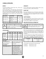
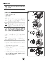
This product is for use on a nominal 120 volt circuit and has a 

grounding plug that looks like the plug illustrated below. Make 

sure that the product is connected to an outlet having the same 

configuration as the plug. No adapter should be used with this 

product.

Grounded Outlet

Grounding Pin 

Cover for grounded outlet box 

Attention

When the sprayer is used with a generator or 

uncontrolled line voltage, the use of Titan’s “Line 

Surge Protector” (P/N 800-935) is recommended.  

i

Make sure to check for grounding continuity 

after service is performed on any electrical 

components.
Use an ohmmeter to determine that there is 

continuity between accessible dead-metal parts 

of the product and the grounding blade of the 

attachment plug.

Summary of Contents for ControlMax 1500

Page 1: ...Form No 0580356C Airless high pressure spraying unit APPAREIL DE PULV RISATION HAUTE PRESSION SANS AIR UNIDAD DE PULVERIZACI N SIN AIRE Y DE ALTA PRESI N F guide d utilisation 24 E manual del uso 46 O...

Page 2: ...an outlet that is properly installed and grounded in accordance with all local codes and ordinances WARNING Improper installation of the grounding plug can result in a risk of electric shock If repair...

Page 3: ...mp at least 20 feet 6 meters from the spray object in a well ventilated area add more hose if necessary Flammable vapors are often heavier than air Floor area must be extremely well ventilated The pum...

Page 4: ...drugs or alcohol Do not kink or over bend the hose Airless hose can develop leaks from wear kinking and abuse A leak can inject material into the skin Do not expose the hose to temperatures or pressu...

Page 5: ...tically shut down after heavy use If this happens turn switch OFF 0 unplug the sprayer and allow to cool for 20 30 minutes and resume spraying Capability Sprays a variety of paints oil based and latex...

Page 6: ...uttons will secure the handle into place Plastic Frame Align the handle to the tabs on the unit and press into place until it snaps no snap buttons Attention Plastic Frame Do not attempt to remove the...

Page 7: ...e hose end with a wrench b Press the hose into the opening in the restraint at the bottom of the gun handle The hose will flex slightly to fit through the smaller opening and then pop into place with...

Page 8: ...lows for easy transport of the material container cart models only 7 Material return tube Fluid is sent out through the return tube and back into the original container when the PRIME SPRAY knob is in...

Page 9: ...1 To lock the trigger flip the trigger lock down until it stops in place behind the trigger 2 To unlock the trigger flip the trigger lock up until it snaps into place on the gun handle pressure relie...

Page 10: ...p cloths or mask anything that is in the spraying area and could accidentally be sprayed 1 Fully depress the pusher stem to make sure the inlet ball is free i The pusher stem will only travel approxim...

Page 11: ...E SPRAY knob to SPRAY 3 Continue to squeeze trigger until the material is flowing freely through the spray gun 4 Perform the Pressure Relief Procedure page 9 5 Make sure the spray gun trigger is locke...

Page 12: ...h h h h 311 h h h h 313 h h h h h 413 h h h h h h 515 h h h h h 517 h h h 619 h Spray Pressure Low Med setting 1 3 Med High setting 3 5 Med High setting 3 5 High setting 5 High setting 5 i The chart a...

Page 13: ...in order to keep gun parallel to the surface correct incorrect Hold the spray gun level i The distance from the spray gun to the spray object should not exceed 18 inches 10 12 25 30 cm correct 10 12 2...

Page 14: ...degrees from its current position i If spray tip is difficult to rotate relieve pressure by 1 slowly turn PRIME SPRAY knob to PRIME 2 unlock the spray gun and 3 squeeze trigger while pointing at scra...

Page 15: ...ls Attention Make sure your floors and furnishings are covered with drop cloths to prevent accidental drips 1 Remove the inlet filter by pulling it off the suction tube 2 Clean the screen using the ap...

Page 16: ...e Pressure Relief Procedure page 9 2 Turn spray tip 90 This will prevent air from drying out any spray material that may be inside the spray tip Wrap spray tip in a damp rag and then place entire spra...

Page 17: ...ay gun 3 Remove the spray tip from the tip guard Place both into a container of the appropriate cleaning solution i It is okay to place the spray tip and tip guard in the same container of cleaning so...

Page 18: ...ing in the black housing on the suction tube that the inlet filter attaches to is completely clean and free from spray material 9 important steP Fill a bucket with warm soapy water Following steps 5 7...

Page 19: ...ht oil can be substituted such as 10W30 motor oil or vegetable oil for example 2 Place a wrench on the outlet valve to secure it Using the second wrench remove the spray hose 3 Fill a cup or other con...

Page 20: ...pring e Take care not to lose any removed parts Visually inspect the removed parts as well as the inside and outside of the inlet valve fitting Inspect the inlet valve housing area where the inlet val...

Page 21: ...ath the outlet valve with a 2 5 mm allen wrench 3 Unscrew outlet valve from outlet valve housing using wrench Remove any accumulated material inside outlet valve housing using appropriate solution for...

Page 22: ...6 The material is too coarse 7 The outlet valve assembly is damaged or worn 8 Spray hose is too long 9 Filter accessory is dirty or plugged 1 Increase the pressure by turning the pressure control knob...

Page 23: ...ship during the applicable warranty period please call Titan Technical Service at 1 866 848 2698 do not return the product to the original retailer Under Titan s Free Tool Replacement Program Titan Te...

Page 24: ...ble de la soupape de sortie Conjunto de la v lvula de salida 5 0580071A 0580071A Inlet valve fitting includes O ring Raccord de la soupape d entr e inclut le joint torique Conexi n de la v lvula de en...

Page 25: ...de la soupape d entr e inclut le joint torique Conexi n de la v lvula de entrada incluye junta t rica 6 0580391 0580391 Inlet valve kit Trousse de la soupape d entr e Kit de v lvula de entrada 7 9885...

Page 26: ...trolMax Pro incluye los elementos 2 a 4 2 353 515 353 515 353 515 Spray tip 515 Embout 515 Boquilla de pulverizaci n 515 3 353 702 353 702 353 702 Spray guard assembly includes item 4 Ensemble anti cl...

Page 27: ...filtre d entr e Carcasa del filtro de entrada 5 0580155 0580155 0580155 Inlet filter Filtre d entr e Filtro de entrada 6 9890222 9890222 9890222 Suction tube clamp Agrafe du tube d aspiration Abrazad...

Page 28: ...619 619 ControlMax Tip Embout de ControlMax 619 Boquilla de ControlMax 619 353 702 ControlMax Tip Guard Prot ge embout ControlMax Protecci n de la boquilla ControlMax Misc Accessories Accessoires div...

Reviews: