TPM 053
Version 1.0, May 30, 2017
Page | 9
MODULE INSTALLATION
Gateway Installation and Operation Manual
Tp
m
053006
Tp
m
053007
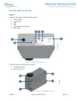
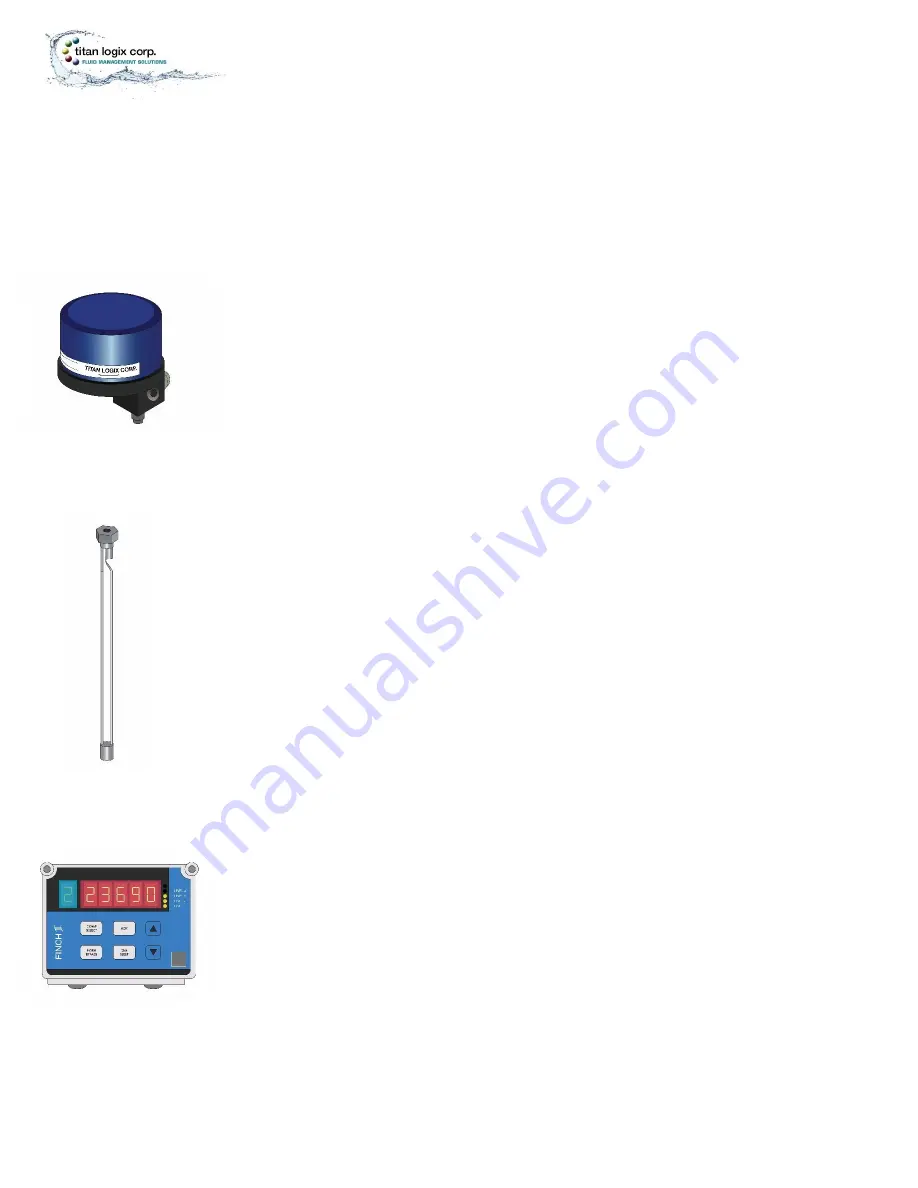
Figure 6
–
TD80 Transmitter
Tp
m
053008
Figure 7
–
TD80
Probe
Figure 8
–
Finch II Display
While the Gateway gathers and streams positioning data to the cloud, the TD80 and Finch II System
work together to display payload information. The TD80 and Finch II System are assumed to be in place
before installation of the Gateway.
TD80
C
OMPONENTS
TD80 Transmitter
The TD80 transmitter generates and processes the Guided Wave Radar signals to
determine liquid level in a tank. The TD80 is mounted on the tank top and connected to
the probe. TD80s are available in two versions, dual rod and coaxial probe for
compatibility with a wide range of liquids.
Probe
The probe guides the transmitted pulse and reflection from the surface of the liquid.
Probes are available in dual rod or coaxial versions and require a matching transmitter
type. The probe is mounted on the tank top and is connected to the bottom of the
transmitter. Dual rod probes are designed for viscous liquids. Coaxial probes are used
mostly for tanks containing products like aviation fuel.
Finch II Display
The Finch II Display is an external use, numeric display of volume information, alarms
and system error codes from the TD80 transmitter. Various alarm and error conditions
are detected by the transmitter and display. These alarm states control four internal
relays for alarm annunciation, high level shutdown and low level prevention.


