19
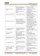
3)Initiates two delays of "WAITING FOR START OF
ACCESS А and В" for each access
individually, which are counted from the moment of acquisition of commands.
4) The controller is waiting for start of access.
5) After rotor is revolved to 6º in any side, opposite direction will be locked LED is
switched to red.
Then the controller is operating as described in section "SINGLE ACCESS IN ONE
DIRECTION". If during active status of the "TO BE OPENED A" and "TO BE OPENED B"
signals or during WAITING FOR START OF ACCESS rotor has not been revolved in any side
to
the angle more than 6º, the controller is switched to the INITIAL STATE
.
1.6.2.3.5
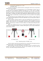
“PANIC” FUNCTION
The turnstile is switched to "PANIC" state:
After the active state is held on input (“INP5” "PANIC") for more than 1 sec;
After "PANIC" command is sent by control panel (the command is sent after
"PANIC" button is held for more than 7 sec.).
After activation of "PANIC" function the barrier rod, which is in horizontal position, will
be dropped, the output (“OUT7” "PANIC") will be switched to active state du
ring the function
action.
The "PANIC" function is canceled:
After active state is released on input “INP5” "PANIC");
After command “CANCELATION of PANIC” is sent from control panel (repeated
pushing of "PANIC" button);
In each case the appropriate command will be issued to the motorized mechanism
controller resulting in rotor rotation and the dropped barrier rod will come to its operating
position and will be fixed (barrier rod locking to be checked manually).
1.6
.2.3.6 «
LOCKING OF ACCESS
»
The locking function can be activated by means of control panel only. After activation of
“LOCKING OF ACCESS A or B” the turnstile rotor is locked in the relevant direction and
access authorization commands will be ignored in the locked direction;
The locked direction is indicated by blinking red color.
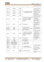
The purpose of controller contacts, designed for connection to peripherals, is specified in
Table 8.
Table 8
Connecto
r /
contact
No.
Description
Direction
Purpose
Signal parameters
and description
ХТ1/1
INP1 («PANIC»)
ENTRY
«SWITCHING TO PANIC
STATE» command
1) logic «0»
(0
2,2) V;
2) Logic «1»
(3
5) V;
3) Active level of
signal (Factory
setting) – Logic
«0»;
4) Voltage on open
input
< 5 V
ХТ1/2
INP2
(«
TO BE OPENED
A
»)
ENTRY
"TO BE OPENED FOR
SINGLE ACCESS" in
pulse mode command.
When this command is
issued entry is activated
within 5 sec.
ХТ1/3
INP3
(«TO BE OPENED
В»)
ENTRY

