background image

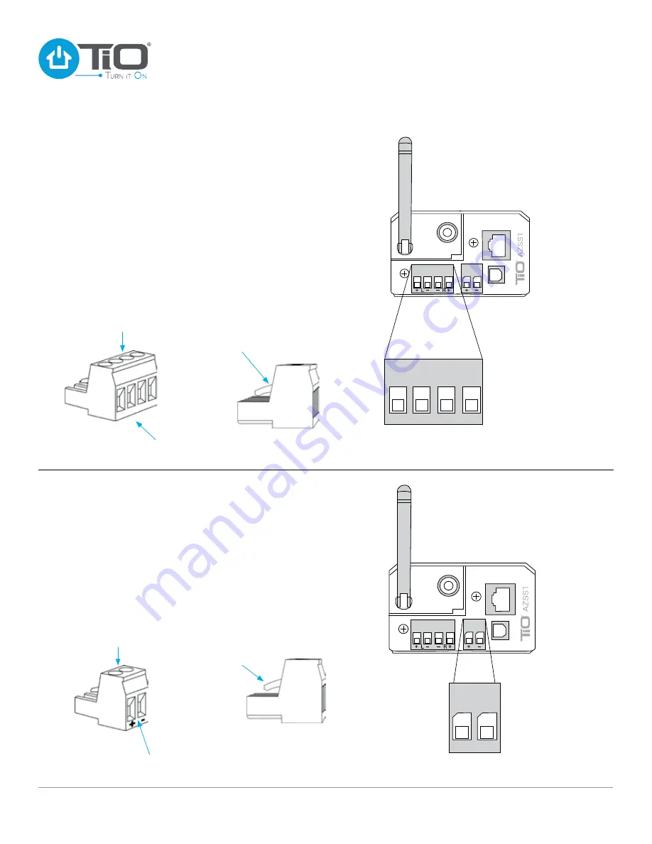
SPEAKER WIRE CONNECTION 

Locate the Speaker Connector Block that came in the pack of 

accessories with your AZSS1. Loosen the four screws before 

attempting to connect the speaker wire. With your speaker wire 

ends trimmed back 1/4” inch (.64 cm) insert each speaker wire 

and tighten down each screw. 

Note the polarity: 

positive (+) 

speaker wire on the outside terminal and negative (–) speaker 

wire on the inside terminal. See diagrams below for wiring 

speakers. 

Note:

 Make sure locking tabs on mating side of Speaker 

Connector locks 

over 

the top of the receiving connector on   

the AZSS1. 

+   L –   

    –   R  +

Lock Tabs Over

Speaker Connector

Removable Speaker 

Connector Block

+   L –       –   R  +

WIRING 

CONNECTIONS

POWER WIRE CONNECTION 

Locate the AZPS1 power supply. To connect the power supply 

to the AZSS1 you will need to locate the Power Connector 

for the AZSS1. The power connector is located in the pack of 

accessories in the AZSS1 package. With the Power Connector 

in your hand, loosen the two screws, so that the two power 

wires can be inserted, then tighten down each screw. 

Note the 

polarity:

 Left positive (+), Right negative (–). Plug the Power 

Connector into the the back of the AZSS1.  

Note:

 Make sure locking tabs on mating side of the Power 

Connector locks 

over 

the top of the receiving connector on   

the AZSS1. 

Removable  

Power Connector

+      – 

Lock Tabs Over

Power Connector

Loosen Screws

Insert Speaker 

Wires

Insert Power

Wires

Loosen Screws

CAUTION 

Be certain the 

polarity is correct

CAUTION 

Be certain the 

polarity is correct

www.tiohome.com

9

StealthStream

®

 1 Installation Guide

Summary of Contents for AZSS1

Page 1: ...StealthStream 1 AZSS1 Installation Guide...

Page 2: ...andard In wall 8 Speaker Wiring Diagrams 8 Speaker Wire Connection 9 Power Wire Connection 9 Variable Output 10 Digital Audio Input Connection 10 System Overview 11 Audio Applications 12 Troubleshooti...

Page 3: ...y If you have any questions call TiO Support at 833 TiO HELP or email us at support tiohome com NOTE This equipment has been tested and found to comply with the limits for a Class B digital device pur...

Page 4: ...usic app to refresh your device list STEP 5 To connect to and use your StealthStream 1 wirelessly perform all of the steps above Once you are in the TiO Music app select the StealthStream 1 you would...

Page 5: ...ut your home Auto switching Switches to the optical input when your TV CD player or cable box is turned on Analog Audio Output Outsource your sound to an Party Mode TiO s StreamShare feature can synch...

Page 6: ...r a cabinet the antenna should be turned upright in the vertical position See Figure 2 Status Light Indicator Used for setting up and troubleshooting your AZSS1 Refer to the troubleshooting guide sect...

Page 7: ...eaker wire TiO recommends 16 gauge speaker wire for multi space audio installations Power Input Removable 2 terminal power connector can support up to 12 gauge wire Wired Ethernet Jack Used for a hard...

Page 8: ...s up properly with the front panel of the AZSS1 Locate the small screws from the installation package Secure the in wall mounting bracket to the front of the AZSS1 STEP 5 Make all wiring connections a...

Page 9: ...S POWER WIRE CONNECTION Locate the AZPS1 power supply To connect the power supply to the AZSS1 you will need to locate the Power Connector for the AZSS1 The power connector is located in the pack of a...

Page 10: ...ttach the optical Line In if adding a digital input source Use a Toslink cable to connect the AZSS1 to any supported External Audio Input Device External Output Devices include Powered Subwoofer A V R...

Page 11: ...System Overview StealthStream 1 Audio Elements www tiohome com 11 StealthStream 1 Installation Guide...

Page 12: ...your application Internet TiO App Home Network Router Stand alone AZSS1 Stand alone application PS PS MasterCoordinator for true Multi space applications up to three in a single house When installed a...

Page 13: ...off for 15 seconds BLINKING BLUE Device is turning on Device is connecting to network No additional steps No additional steps SOLID GREEN Successfully connected No additional steps SOLID BLUE Device i...

Page 14: ...ure has occurred due to a defect in materials or workmanship b Cosmetic damage including but not limited to scratches dents cracks or other cosmetic damage c Damage caused by use with non TIO products...

Page 15: ...al loss arising out of or in connection with the ability or inability to use the products Some states or jurisdictions do not allow the limitation or exclusion of incidental or consequential damages o...

Page 16: ...ns overall 6 99W x 4 78H x 9 91D cm 2 75W x 1 88H x 3 90D in Weight 249g 55lb Connectivity Wired or Wireless 802 11n 2 4GHz Ethernet Bluetooth version 3 0 Max Output 100W 4 Ohms 0 1 THD N 1kHz Frequen...

Reviews: