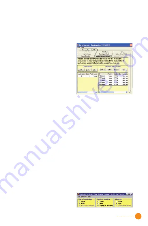
activation/deactivation field column for each non-functional end node.
The
Yes
field will change to
No
. Also, note that if more than five units
are being installed, you must add rows to represent these additional
units. See the
Software Operations Manual for more details.
6. Select the first row in the
controller table. Click the
Delete
button. Click the
Find
button. A
Notepad file is displayed
showing all of the com ports
scanned in finding the controller.
The Notepad display can show
you information about your
computer that can help diagnose
problems with com ports. See
Figure 3.1.
Figure 3.1 ———————————
7. Cancel the Notepad display. The controller’s table should now contain
the address and com port that your controller is attached to. Select
the location field and enter the location of the controller for
documentation purposes. If the Find procedure did not locate your
controller, add a row to the controller table and fill in the fields
accordingly.
8. To complete the software configuration select from the menu
File
then
Generate System
. After the system has been generated, select from
the menu
File
and
Exit
.
9. To run the system, double click the StatusCheck icon on the PC’s
desktop. This time the monitoring software will execute. The controller
window will be displayed. See Figure 4 below. To see if all of your
installed devices are working click the
Show
radio button under
System Monitor
on the controller window. If you want to see the real-
time data being gathered, click the
Show
radio button under
Grapher
.
If you need additional information on how to configure or use the
monitoring software, please refer to the
Software Operations Manual.
If some devices in your system are not working, see the
troubleshooting guide in the
Hardware Operations Manual.
Figure 4 ————————————
3
Summary of Contents for StatusCheck
Page 1: ...StatusCheck Operators Manual StatusCheck 2 4GHz ...
Page 23: ......


