Note:
The controller, when interfaced with a PC, must be configured
properly; open the hinged lid and ensure the router/controller switch
inside the box is set to “controller.” Close and secure the lid.
4. After step 3 is complete, double click the StatusCheck icon that
appears on the PC’s desktop. The
icon will appear after the
software installation step is
completed.
A dialog box will appear telling you
that your software needs configured.
Click the
OK
button on the dialog
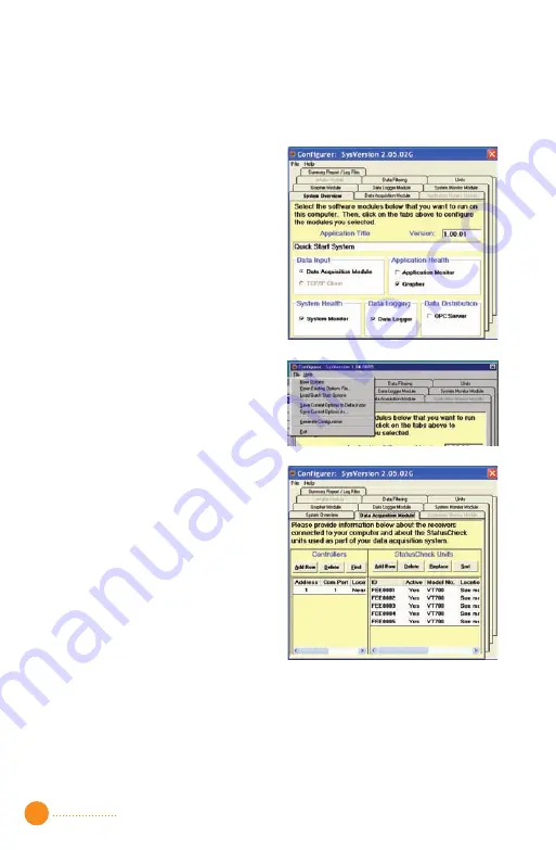
box. A window with multiple tabs will
appear. See Figure 1.
Figure 1 ————————————
Select from the menu
File
, then
select
Load Quick Start Options
.
See Figure 2.
Figure 2 ————————————
After the options have loaded, click
the
Data Acquisition Module
tab.
You will see five generic end node
ID’s, from FEE0001 to FEE0005, in the
end node table. These need to be
replaced by the ID numbers specific
to your system. See Figure 3.
Figure 3 ————————————
5. Select the row with end node ID FEE0001. Click the
Replace
button. A
dialog box will ask you for the new end node ID. Enter the ID from one
of the end nodes you installed in step 1. If you have installed more end
nodes, repeat this step for each end node using rows with end node
IDs FEE0002, FEE0003, and so on. If there are rows present that do not
represent end nodes you have placed in the field, double click on the
2
Summary of Contents for StatusCheck
Page 1: ...StatusCheck Operators Manual StatusCheck 2 4GHz ...
Page 23: ......


