10
Mounting Methods:
The StatusCheck end node attaches externally to the frame of the
monitored machine. End node mounting must not interfere with normal
machine operations.
The StatusCheck end node can be mounted at any location along the
machinery frame or housing. For best results, it should be positioned as
close as possible to the source of vibration. This provides the best signal.
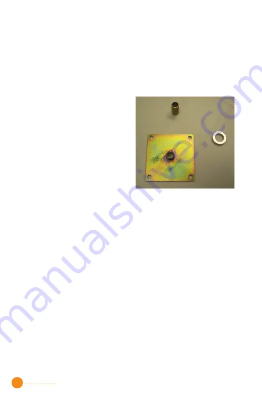
The StatusCheck end node can be
permanently or temporarily secured
to the monitored machine. The
magnet mounting allows movement
of the end node to other locations for
quick testing, however the
recommended mounting methods
are the threaded nipple or tack weld
plate. Threaded mounting options
are shown on Figure 9.
Figure 9: Threaded Mounting Options
Installation of the End Node:
The end node can be mounted to a machine using the magnet, the
threaded nipple or tack weld plate. Testing has shown that the use of
threaded mounting results in improved accuracy of high frequency
vibration measurement. Therefore, the threaded mount method is
recommended.
Caution:
The magnet pull force is 110 N (25 lbs.), which may not be
sufficient to hold the end node in place on vibrating machinery. This may
create an overhead drop hazard.
Threaded mounts are available in 16M threaded fittings or plates that are
tack-welded or riveted to the machine. If the plate is used, it should be
rigidly attached to a relatively flat portion of the machine surface. When
using the threaded mount, a torque of 3.95Nm (35 in-lbs.) will yield
accurate measurements. Torque in excess of 3.95Nm (35 in-lbs.) may
damage unit housing.
The end node can be mounted in any orientation. The end node axes
should be parallel to the desired measurement axes. Refer to Figure 7 for
end node axes orientation. The Z-axis is parallel to the direction of the
temperature probe. The X-axis is positioned along the direction of the
Summary of Contents for StatusCheck
Page 1: ...StatusCheck Operators Manual StatusCheck 2 4GHz ...
Page 23: ......


