background image

TMS6002 
USER MANUAL 

Ref :  MN06127 

Date :  2019-03-27


Issue :  A1 

Page:  5/18 


Tous droits réservés © TimeLink microsystems


1.2.


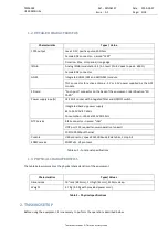
DETAILED CHARACTERISTICS 


 Characteristics 

Types / Value 

1PPS output 

Level: 0-5V, positive pulse, 50 Ohms 

Female BNC connector – named "1PPS" 

Duration: 20us, 1Hz period, rising edge 

IRIG-B 

Analog IRIGB (modulation 1:3/1:1, level 0 to 8V peak to peak - 600 Ω) 

Female BNC connector 

GNSS  

Integrated GNSS (GPS and GLONASS) module 

TNC  connector  for  active  antenna - 5V or 3.3V power supplied by the GPS 
module  

SD card 

"Push-push" connector on the back of the equipment - Identification "SD 
CARD" 

Power supply input(s) 

CEE 2P+E socket with integrated filter and ON/OFF switch 

Integrated back-up power supply 

85 to 265V AV 47-60Hz 

Consumption : <10W at 230VAC/50 Hz 

NTP Service 

RJ45 connector – named  "LAN" 

UDP port 123, request/answer operation (unicast) 

100/1000 Mbps Ethernet 

Console 

USB connector, speed 115200 bauds, 8 data bits, 1 stop bit 

SNMP service 

SNMP v2c, V3 protocol 


Tableau 1 – functional specifications 

1.3.


PHYSICAL CHARACTERISTICS 

The table below summarizes the physical characteristics of the equipment. 


Characteristics 

Types/Values 

Dimensions 

19" rack (483 mm), 1U high (44 mm), 350 mm deep. 

Weight 

2.7 Kg (3.0 Kg with provided power cord). 


Table 2 – Physical specifications


2.


TMS6002 SETUP 

Before using the equipment, it is necessary to perform the operations described below.  

Summary of Contents for MN06127

Page 1: ...Tous droits r serv s TimeLink microsystems TMS6002 USER MANUAL Reference MN06127 Issue A1 Date 2019 03 27...

Page 2: ...TMS6002 USER MANUAL Ref MN06127 Date 2019 03 27 Issue A1 Page 2 18 Tous droits r serv s TimeLink microsystems Version change Issue Date Description A1 2019 03 27 Original issue...

Page 3: ...NG UP 9 3 2 LEDS 9 3 3 SCREENS 10 3 3 1 MAIN SCREEN 10 3 3 2 ALARMS SCREEN 11 3 3 3 SOURCE SCREEN 11 3 3 3 1 GNSS SCREEN 11 3 3 3 1 IRIGB SCREEN 12 3 3 4 OSCILLATOR SCREEN 12 3 3 5 EQUIPMENT INFORMATI...

Page 4: ...riority selection amongst them The equipment will automatically switch from one to the other source if the current source is not usable anymore 1 1 FRONT AND BACK PANEL The front panel of the device h...

Page 5: ...ARD Power supply input s CEE 2P E socket with integrated filter and ON OFF switch Integrated back up power supply 85 to 265V AV 47 60Hz Consumption 10W at 230VAC 50 Hz NTP Service RJ45 connector named...

Page 6: ...TION The proper functioning of the equipment requires setting the configuration parameters with consistent values These settings are located on an SD card inserted in the back of the equipment The par...

Page 7: ...ty of the source compare to the others 1 is highest priority Mandatory 1 1 2 3 IRIGB_IN Select the priority of the source compare to the others 1 is highest priority Mandatory 2 1 2 3 LOCAL Select the...

Page 8: ...can be activated Mandatory N Y or N BEIDOU Enable or disable BEIDOU constellation Only 2 constellations can be activated Mandatory N Y or N Note any change to the default constellation must be followe...

Page 9: ...5 notrust authenticated 3 HOW TO GET STARTED 3 1 POWERING UP The equipment power up when the power is applied to the unit and the ON OFF switch is turned ON 3 2 LEDS On the front panel a group of thre...

Page 10: ...efault screen It provides a synthesis of the operation of the equipment The displayed information is the following current UTC date and time name of the selected time source GNSS or LOCAL quality of t...

Page 11: ...hen multiple alarms are up the left and right arrow keys can be used to navigate around them The number of alarms is shown is the upper right corner with the syntax X N where X is the X th alarm out o...

Page 12: ...no signal in that case A long press on the red button excludes or includes the IRIGB source into the list of available time sources 3 3 4 OSCILLATOR SCREEN This screen gives information about the meas...

Page 13: ...e the software modify the password of a user restart or stop the equipment connect as root The default password for both accounts is timelink 3 4 1 CHANGE PASSWORD To change the password for a user us...

Page 14: ...change its identity to root To do this type tools su and enter the root password 3 5 SERIAL CONSOLE ACCESS Access to the system can also be made from the Console port by connecting a terminal emulator...

Page 15: ...ccuracy The Time sources section provides control over the available time sources as shown below A right click on the source allows excluding or including the selected source 4 2 SNMP MONITORING The m...

Page 16: ...card reader of a PC Use a text editor to modify the user ini file The SD card can then be located back into the equipment which needs to be powered on Important note Depending on the used text editor...

Page 17: ...TMS6002 USER MANUAL Ref MN06127 Date 2019 03 27 Issue A1 Page 17 18 Tous droits r serv s TimeLink microsystems 3102 GNSS time is different from internal...

Page 18: ...TMS6002 USER MANUAL Ref MN06127 Date 2019 03 27 Issue A1 Page 18 18 Tous droits r serv s TimeLink microsystems Fin du document...

Reviews: