


Micro Lynx ACG Option Card
ECC NO. 1019
Page 8
73630 REV. C
19. Power up the System Unit. The Micro Lynx will recognize the ACG Card on power
up and the ACG LED on the System Unit OPTION Section will turn on. Press
SETUP
,
ACG
, to configure the card functions.
PROCEDURE (continued):
System Unit Serial Numbers 1954 and higher (ACG option bracket pre-fitted)
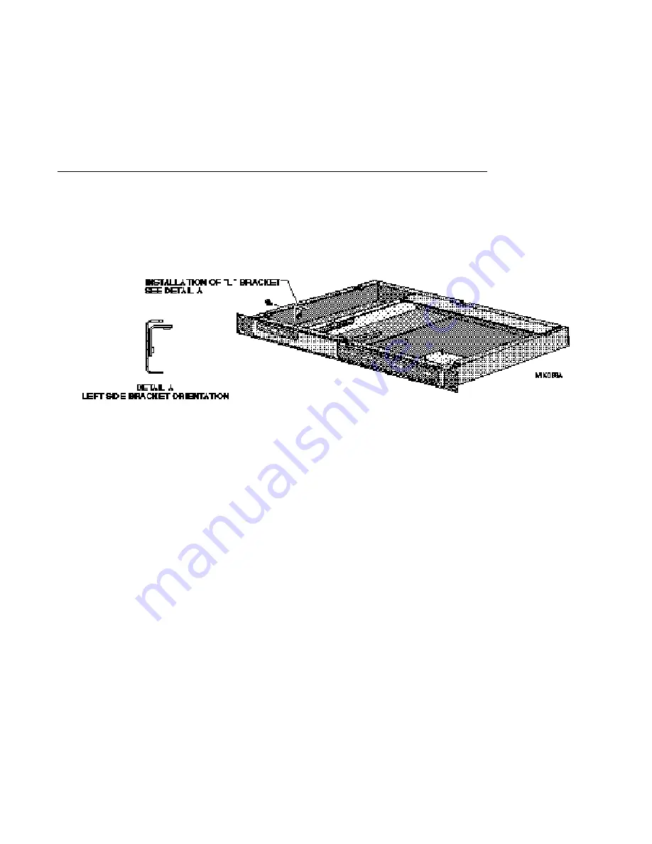
Install the ACG Option Card “L” Bracket
5. Locate the “L” shaped bracket in the ACG Option Card Kit. Install this bracket to the
left side of the chassis as shown in Detail A and secure using the phillips screw
supplied in the kit. (See Figure 8.)
Figure 8. Location of "L" Bracket
6. Remove the mounting standoff from the 9-pin connector on the ACG Card.
7. The Option Card cable is a ribbon cable with four connectors attached. On one end of
the cable, the second connector is about 3.5" from the end. Insert this end into
connector J1 on the component side of the ACG Card. The connector should be
attached so that the cable falls away from the ACG Card, as illustrated in Figure 3.
8. Position the ACG Card component side down with connector J1 toward the front of the
System Unit. Approximately 1.25" from the J1 connector, bend the Option Card cable
under, so that it makes a right-angle turn (the unused connectors on the cable will face the
chassis bottom).
9. Insert the folded Option Card cable through the opening in the Option Card bracket.
10. Lie the ACG Card flat on the Option Card bracket. Slide the ACG Card against the
back panel, so that the
AES/EBU
connector and the
O.S. OUT
,
WORD OUT
and
CLOCK IN
jacks are seated in the appropriate cutouts in the back panel. Insert the washers and
nuts onto the BNC connectors. Replace the mounting standoffs on the 9-pin connector.
11. The corner of the ACG Card, with the black rubber bumper, will rest on the “L”
bracket installed on the side of the chassis in Step 5. Insert two phillips screws
through the ACG Card into the Option Card bracket and tighten. (See Figure 9.)


