


C190-0308 - Rev 1.0 EN
53/66
5.19.4
Removing the Rubber Tracks
Removing a rubber track from the base requires a degree of manual force and must
only be carried out in a safe working environment to prevent the possibility of
damage to the machine or injury to the operator.
1.
Ensure that the rubber track to be removed is safely raised from the ground, and
securely supported. (Refer to Section 1.1 "Track Base Maintenance" on page 1.)
2.
Loosen the track to enable its removal (Refer to Section 1.0.1 "Adjusting Track
Tension" on page 1).
3.
Remove the track from the adjustable, track-stretching sprocket first.
4.
Using appropriate levers, prise the track sideways to slide it off the sprocket. (Take
care not to damage the track or any supporting structure.)
5.
Move to the other end of the track base and remove the track from the drive sprocket.
With the track removed, the sprockets should be examined for signs of wear. There
should always be sufficient tooth left on the sprocket to fully engage with the rubber track.
If the meshing distance is significantly reduced the sprocket should be changed
5.19.5
Fitting the Rubber Tracks
Fitting a rubber track to the base requires a degree of manual force and must only be
carried out in a safe working environment to prevent the possibility of damage to the
machine or injury to the operator.
1.
Ensure that the side of the machine where the track is to be fitted is safely raised from
the ground, and securely supported. (Refer to Section 5.19 "
2.
Ensure that the grease in the adjustment unit is removed and the track-stretching
sprocket is retracted to it's minimum length. (Refer to Section 5.19.3 "
3.
Locate the track on the drive sprocket first, ensuring the links mesh correctly with the
sprocket teeth.
4.
Move to the other end of the track base and locate the track on the track-stretching
sprocket , ensuring the links mesh correctly with the sprocket teeth . Appropriate
levers may be required to engage the track with the sprocket. (Take care not to
damage the track or any supporting structure.)
5.
Set the track tension. (Refer to Section 5.19.3 "
Adjusting Track Tension" on page
52.)
6.
Lower the machine to the ground. (Refer to Section 5.18 "
page 49.)
5 Maintenance Instructions
TW 280FTR (Petrol)
Summary of Contents for TW 280FTR (Petrol)
Page 1: ...C190 0308 Rev 1 0 EN TW 280FTR Petrol Wood Chipper INSTRUCTION MANUAL Original Instructions...
Page 6: ...4 66 C190 0308 Rev 1 0 EN TW 280FTR Petrol THIS PAGE INTENTIONALLY LEFT BLANK...
Page 24: ...22 66 C190 0308 Rev 1 0 EN TW 280FTR Petrol THIS PAGE INTENTIONALLY LEFT BLANK...
Page 56: ...54 66 C190 0308 Rev 1 0 EN TW 280FTR Petrol THIS PAGE INTENTIONALLY LEFT BLANK...
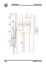
Page 57: ...C190 0308 Rev 1 0 EN 55 66 6 Electrical System 6 Electrical System TW 280FTR Petrol...
Page 58: ...56 66 C190 0308 Rev 1 0 EN TW 280FTR Petrol 6 Electrical System...
Page 59: ...C190 0308 Rev 1 0 EN 57 66 7 Hydraulic System 7 Hydraulic System TW 280FTR Petrol...
Page 60: ...58 66 C190 0308 Rev 1 0 EN TW 280FTR Petrol THIS PAGE INTENTIONALLY LEFT BLANK...
Page 64: ...62 66 C190 0308 Rev 1 0 EN TW 280FTR Petrol THIS PAGE INTENTIONALLY LEFT BLANK...
Page 67: ...C190 0308 Rev 1 0 EN 65 66 10 Notes 10 Notes TW 280FTR Petrol...
Page 68: ...C190 0308 Rev 1 0 EN...