background image

5.19

Track Base Maintenance

WARNING

ALWAYS ENSURE THAT THE CHIPPER IS CORRECTLY AND

SAFELY SUPPORTED FOR ANY OPERATIONS THAT REQUIRE IT

TO BE RAISED FROM THE GROUND.

1.

Ensure the chipper is correctly supported (Refer to Section 5.18 "

Jacking the Chipper"

on page 49.

2.

Hydraulic systems may get very hot after working.

3.

Keep all components in good condition as they are exposed to high pressures.

4.

Immediately repair damage and replace worn or broken items.

5.

Keep the tracks clean, removing excess oil, grease and dirt.

6.

Check for oil leaks and damaged hoses.

7.

Only use recommended lubricants. Do not mix different brands.

8.

Keep the track adjuster unit grease nipples clean.

5.19.1

Checking Track Tension

To prevent damage to the rubber tracks they should be checked every day to ensure they
are at the correct tension.

1.

Stop the machine on a flat and solid surface
and turn the engine off.

2.

Measure from the ground to the inside edge
of the track at the top central location (Figure
36
, Item 1).

3.

Pull the top centre of the track firmly

upwards and measure the deflection from
the initial measurement (Figure 36, Item 2).

4.

The track tension is correct if the deflection

is between 30 mm and 40 mm.

5.

If the deflection is outside the recommended
limits, the track tension should be adjusted.
(Refer to Section 5.19.3 "

Adjusting Track

Tension" on page 52.)

Figure 36 - Checking Track Tension

50/66

C190-0308 - Rev 1.0 EN

TW 280FTR (Petrol)

5 Maintenance Instructions

Summary of Contents for TW 280FTR (Petrol)

Page 1: ...C190 0308 Rev 1 0 EN TW 280FTR Petrol Wood Chipper INSTRUCTION MANUAL Original Instructions...

Page 2: ...peraar nl Australian timberwolfchippers com au Copyright Copyright 2020 Timberwolf All Rights Reserved Contains information owned by Timberwolf and or its affiliates Do not copy store transmit or disc...

Page 3: ...s Locator 2 9 2 2 3 Parts Locator 3 10 2 2 4 Parts Locator 4 11 2 3 Tool Box 11 2 4 Safety Decals 12 2 5 Instruction Decals 13 2 6 Model Decals 15 2 7 Identification Plate 16 2 8 Guards 16 3 Safety No...

Page 4: ...4 13 Stopping the Engine 30 4 14 Blockages 31 4 15 Blade Wear 31 4 16 Check Hydraulic Oil Level 32 4 17 Check Hydraulic Oil Temperature 32 4 18 Check Fuel Level and Refuel 33 4 19 Winch Operation 33...

Page 5: ...ing the Chipper 49 5 19 Track Base Maintenance 50 5 19 1 Checking Track Tension 50 5 19 2 Checking the Rubber Tracks 51 5 19 3 Adjusting Track Tension 52 5 19 4 Removing the Rubber Tracks 53 5 19 5 Fi...

Page 6: ...4 66 C190 0308 Rev 1 0 EN TW 280FTR Petrol THIS PAGE INTENTIONALLY LEFT BLANK...

Page 7: ...hat all operators are properly trained for operating the TW 280FTR especially in safe working practices Timberwolf s policy of regularly reviewing and improving our products may involve major or minor...

Page 8: ...EFER TO THESE FOR FIRST AID AND FIRE PROTECTION MEASURES Always follow recommended procedures for safe handling removal and disposal of hazardous materials Safety precautions should be taken when hand...

Page 9: ...Height 2320 mm Height with Discharge Tube Removed 1460 mm Length with tray and step up 2880 mm Length with tray and step down 3665 mm Width 1410 mm Overall Weight 1592 Kg Without Winch Engine Type Kub...

Page 10: ...ving control panel 16 Safety bar 6 Driving platform 17 In feed funnel 7 Engine bay side panel both sides 18 Manual canister 8 Rotor housing 19 Push stick Timberwolf Safety Plus Kit 9 Winch controls op...

Page 11: ...1 0 EN 9 66 2 2 2 Parts Locator 2 1 Lifting eye 6 Fuel pump 2 Air filter 7 In line fuel filter 3 Radiator 8 Fuel tank 4 Battery 9 Hydraulic tank 5 Engine block 10 Hydraulic filter 2 Product Details TW...

Page 12: ...r 3 1 Jack 6 Electrical panel 2 Directional control valve 7 Hydraulic pump pulley 3 Top roller slide 8 Exhaust 4 Control panel 9 Oil filter 5 Greasing panel 10 66 C190 0308 Rev 1 0 EN TW 280FTR Petrol...

Page 13: ...ic pump 3 Belt tensioning pulley 8 Fan section x4 4 Drive belts 9 Cutting blade x2 5 Drive pulley 2 3 Tool Box The TW 280FTR is supplied with a tool box which contains Combination spanner 17mm 19mm Ac...

Page 14: ...engine to cool for one minute before refuelling Use unleaded petrol only P653 DANGER Rotating blades inside Stop engine and remove key before removing discharge unit P654 CAUTION When transporting di...

Page 15: ...ting eye to be inspected every 6 months and prior to each use Do not use lifting eye if damaged 3022 Clean under blades before refitting or turning Failure to do so may result in blades coming loose a...

Page 16: ...orward latch P1811 Relay decal Engine safety P1812 Torque blade bolts to 170 Nm 125 ft lb P2157 Relay decal Tracking speed C192 0145 Lifting eye maximum weight C192 0196 Track control panel C192 0202...

Page 17: ...y the machine C192 0146 Wolftrack system C192 0147 Equivalent Continuous Sound Power Level The average amount of acoustic energy an operator is subjected to during normal operations C192 0192 Timberwo...

Page 18: ...er Protects the operator from injuries from moving rollers or from ejected material during operation Hydraulic Motor Guard Protects the hydraulic motors from damage Protects the operator from injuries...

Page 19: ...al Protective Equipment PPE DO NOT wear rings bracelets watches jewellery loose fitting clothing or any other items that could be caught in the material and draw you into the chipper Chainsaw safety h...

Page 20: ...he material to be chipped before you start Avoid confined spaces and use respiratory protection where necessary BE AWARE when the chipper is processing material that is an awkward shape The material c...

Page 21: ...YOU MUST keep the operating area clear of people and animals YOU MUST keep the operating area clear from debris build up YOU MUST keep clear of the discharge tube Material may be ejected with great f...

Page 22: ...machine as serious damage is possible 3 6 Noise Emissions The TW 280FTR has been tested according to BS EN ISO 3744 2010 as required by Annex III of Directive 2000 14 EC Noise Emission in the Environ...

Page 23: ...S EN 12096 1997 Whole Body Vibrations m s2 Hand Arm Vibrations m s2 Speed 1 2 5 kph Speed 2 5 kph Speed 1 2 5 kph Speed 2 5 kph Values determined when standing on driver s platform tracking over soft...

Page 24: ...22 66 C190 0308 Rev 1 0 EN TW 280FTR Petrol THIS PAGE INTENTIONALLY LEFT BLANK...

Page 25: ...2 Item 2 Figure 2 Manual Control Positions Forward Feed Control Figure 3 Press the GREEN control to start the in feed rollers turning in the forward direction if the engine speed is high enough Refer...

Page 26: ...ition key before approaching the roller 4 2 No Stress Control The No Stress function prevents excessive loads being placed upon the engine when feeding larger material into the chipper If the engine s...

Page 27: ...the top of the funnel or either side of the feed tray will remove all power to the engine AND the feed rollers bringing the whole machine to a complete stop The engine cannot be restarted until the op...

Page 28: ...s an engine fault Stop the machine immediately and seek further assistance from a Timberwolf dealer 4 6 Crawler Track Controls WARNING NEVER LEAVE THE CHIPPER ON A SLOPE UNATTENDED NEVER TRANSPORT PAS...

Page 29: ...lever directly controls the track on the corresponding side of the machine forward or backward independently Figure 11 The Track Control Valves are proportional in their operation The further they are...

Page 30: ...HECK for any visible signs of fluid leaks 8 CHECK fuel and hydraulic levels are correct Refer to Section 4 16 Check Hydraulic Oil Level on page 32 and Section 4 18 Check Fuel Level and Refuel on page...

Page 31: ...ed in an emergency resulting in serious injury or death 1 Ensure the engine is running at full speed 2 Lower the feed tray to the working position 3 Press the red safety bar once to activate the contr...

Page 32: ...always turn at the same speed If one or both rollers stop or suddenly slow down it may be that a piece of wood has become stuck behind one of the rollers If this occurs press the BLUE reverse feed co...

Page 33: ...speed 9 Allow the machine time to clear any remaining debris from the rotor housing 10 Feed in a small piece of brushwood and confirm it is ejected correctly 11 If the machine appears to still be bloc...

Page 34: ...perature should not exceed 65oC If it does stop the machine immediately and investigate the cause Failure to do so may result in damage Overheating may result from the chipper working hard in hot cond...

Page 35: ...n the feed funnel Fuel storage containers must be approved for appropriate fuel storage and clearly labelled with securely fitting caps Clean the area around the fuel cap and use a funnel for refuelli...

Page 36: ...e machine is off and keys removed Rotor jammed Inspect clear infeed funnel roller box rotor housing Ensure machine is off and keys removed Drive belt issue Inspect drive belts replace if required Tens...

Page 37: ...chanical maintenance and apply them throughout this machine The failure to apply generally accepted standards of maintenance or the performance of inappropriate maintenance or modifications may invali...

Page 38: ...eck Hoses on page 46 Check fuel level Refer to Section 4 18 Check Fuel Level and Refuel on page 33 Check feed funnel feed roller cover access covers engine covers and discharge unit are securely fitte...

Page 39: ...to this may invalidate warranty and or shorten engine life 5 5 Safe Lifting of the Chipper The lifting eye on the TW 280FTR is only designed to lift the machine s weight for loading unloading etc It...

Page 40: ...t an authorised collection point Never dispose of old batteries in household waste 1 Storage and Transport Batteries are filled with acid Always store and transport batteries upright and prevent from...

Page 41: ...y charged when the charging voltage has stopped rising for two hours 5 Maintenance Keep the battery clean and dry Use a moist anti static cloth only to wipe the battery otherwise there is a danger of...

Page 42: ...e they have not worked loose They should be tightened to the correct torque using a calibrated torque wrench Refer to Table 5 An uncalibrated torque wrench may be inaccurate by as much as 25 and resul...

Page 43: ...also prevents possible injury due to the engine compression suddenly moving the rotor Refer to Section 5 9 Adjust Rotor Drive Belt Tension on page 43 3 Remove the three nuts and washers retaining the...

Page 44: ...is recommended Figure 24 15 Tighten the blade bolts to the correct torque setting Refer to Section 5 7 Check and Replace Fasteners on page 40 Figure 24 Blade Mounting 16 Remove the locking bar from th...

Page 45: ...ble to slide with minimal wobble Figure 25 Item 1 3 Turn the nut on the end of the tensioner pulley slider until the correct belt tension is achieved Figure 25 Item 2 Refer to Section 5 11 V Belt Tens...

Page 46: ...only one belt use a straight edge Take the reading from the deflection scale of the tension meter read at the lower edge of the O ring and compare with the value given in Table 7 for the rotor drive b...

Page 47: ...ulleys Figure 28 Hydraulic Pump Belt Layout TW 280FTR Manufacturer Gates Type Quad Power III Pitch Designation XPA Length 1000 mm Deflection h 2 43 mm Force Kg New Belt 1 13 1 21 Used Belt 0 98 1 06 T...

Page 48: ...Refill with hydraulic oil VG32 to between the Min and Max lines on the tank 50 litres Figure 29Figure 29 10 Refit the filter cup with a new filter element and refit the black screw cap Ensure the O r...

Page 49: ...become dry the top roller may hang up and the pulling in power of the rollers will be reduced This may lead to excessive wear DO NOT USE GRAPHITE BASED GREASE 1 Ensure the chipper is in a safe condit...

Page 50: ...igns of insufficient grease include squeaking or knocking rollers DO NOT USE GRAPHITE BASED GREASE Figure 33 Greasing Panel It is recommended to grease all the nipples whilst the engine is running and...

Page 51: ...h a jacking beam which can be extended from either side of the machine to enable it to be safely raised for maintenance A correctly rated jack is supplied with the chipper stowed on the chassis beam b...

Page 52: ...ep the track adjuster unit grease nipples clean 5 19 1 Checking Track Tension To prevent damage to the rubber tracks they should be checked every day to ensure they are at the correct tension 1 Stop t...

Page 53: ...used by Build up of stones or foreign matter between track and frame Track slipping off its guide system Extreme friction such as rapid changes of direction Improper contact between the track and the...

Page 54: ...the sprocket and the track link before attempting to adjust the track tension 2 Remove the cover plate from the side frame to access the adjustment unit grease nipple see Figure 38 3 To reduce the tr...

Page 55: ...he sprocket should be changed 5 19 5 Fitting the Rubber Tracks Fitting a rubber track to the base requires a degree of manual force and must only be carried out in a safe working environment to preven...

Page 56: ...54 66 C190 0308 Rev 1 0 EN TW 280FTR Petrol THIS PAGE INTENTIONALLY LEFT BLANK...

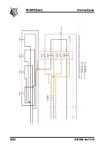
Page 57: ...C190 0308 Rev 1 0 EN 55 66 6 Electrical System 6 Electrical System TW 280FTR Petrol...

Page 58: ...56 66 C190 0308 Rev 1 0 EN TW 280FTR Petrol 6 Electrical System...

Page 59: ...C190 0308 Rev 1 0 EN 57 66 7 Hydraulic System 7 Hydraulic System TW 280FTR Petrol...

Page 60: ...58 66 C190 0308 Rev 1 0 EN TW 280FTR Petrol THIS PAGE INTENTIONALLY LEFT BLANK...

Page 61: ...6 Battery Safety Information on page 38 7 Touch up damaged paint or protect with a suitable lubricant 8 2 Storage Conditions Regardless of storage time the chipper must always be stored in a stable po...

Page 62: ...on 4 Ensure the feed funnel is free from foreign objects e g tools or clothing 5 Open and close the feed tray to ensure it operates correctly 6 Check fuel engine oil and hydraulic fluid levels and top...

Page 63: ...ks Before Starting on page 28 17 Start the engine 18 Run for 15 minutes at half throttle to clear the engine 19 Run for a further 5 minutes at full throttle prior to any cutting activity Storage fluid...

Page 64: ...62 66 C190 0308 Rev 1 0 EN TW 280FTR Petrol THIS PAGE INTENTIONALLY LEFT BLANK...

Page 65: ...ructions on page 35 Pay attention to parts with mechanical pressure or tension applied including springs Separate items that continue to have a service life Separate worn items into material groups an...

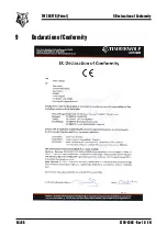
Page 66: ...9 Declaration of Conformity 64 66 C190 0308 Rev 1 0 EN TW 280FTR Petrol 9 Declaration of Conformity...

Page 67: ...C190 0308 Rev 1 0 EN 65 66 10 Notes 10 Notes TW 280FTR Petrol...

Page 68: ...C190 0308 Rev 1 0 EN...

Reviews: