


When using an oscilloscope probe in 1:1 the setting, the bandwidth of the
probe is only 6 MHz. The full bandwidth of the probe is only obtained in
the 1:10 setting
The x10 attenuation is achieved by means of an attenuation network. This atten-
uation network has to be adjusted to the oscilloscope input circuitry, to guaran-
tee frequency independency. This is called the low frequency compensation. Each
time a probe is used on an other channel or an other oscilloscope, the probe must
be adjusted.
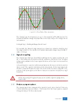
Therefore the probe is equiped with a setscrew, with which the parallel capacity
of the attenuation network can be altered. To adjust the probe, switch the probe
to the x10 and attach the probe to a 1 kHz square wave signal.
Then adjust
the probe for a square front corner on the square wave displayed. See also the
following illustrations.
Figure 3.6: correct
Figure 3.7: under compensated
Figure 3.8: over compensated
10
Chapter 3
Summary of Contents for Handyscope HS4
Page 1: ...Handyscope HS4 User manual TiePie engineering...
Page 6: ......
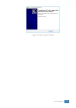
Page 17: ...Figure 4 3 Driver install Finished Driver installation 13...
Page 18: ...14 Chapter 4...
Page 20: ...16 Chapter 5...
Page 22: ...18 Chapter 6...
Page 26: ...22 Chapter 7...
Page 30: ...26 Chapter 8...
Page 32: ...TiePie engineering Handyscope HS4 instrument manual revision 2 27 February 2020...


