


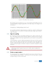


Figure 3.5: The effect of the resolution
The Handyscope HS4 measures at e.g. 12 bit resolution (
2
12
=4096 levels). The
smallest detectable voltage step depends on the input range. This voltage can be
calculated as:
V oltageStep
=
F ullInputRange
/
LevelCount
For example, the 200 mV range ranges from -200 mV to +200 mV, therefore the
full range is 400 mV. This results in a smallest detectable voltage step of 0.400 V /
4096 = 97.65
µ
V.
3.4
Signal coupling
The Handyscope HS4 has two different settings for the signal coupling: AC and
DC. In the setting DC, the signal is directly coupled to the input circuit. All signal
components available in the input signal will arrive at the input circuit and will be
measured.
In the setting AC, a capacitor will be placed between the input connector and the
input circuit. This capacitor will block all DC components of the input signal and
let all AC components pass through. This can be used to remove a large DC com-
ponent of the input signal, to be able to measure a small AC component at high
resolution.
When measuring DC signals, make sure to set the signal coupling of the
input to DC.
3.5
Probe compensation
The Handyscope HS4 is shipped with a probe for each input channel. These are
1x/10x selectable passive probes. This means that the input signal is passed
through directly or 10 times attenuated.
Introduction
9
Summary of Contents for Handyscope HS4
Page 1: ...Handyscope HS4 User manual TiePie engineering...
Page 6: ......
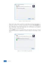
Page 17: ...Figure 4 3 Driver install Finished Driver installation 13...
Page 18: ...14 Chapter 4...
Page 20: ...16 Chapter 5...
Page 22: ...18 Chapter 6...
Page 26: ...22 Chapter 7...
Page 30: ...26 Chapter 8...
Page 32: ...TiePie engineering Handyscope HS4 instrument manual revision 2 27 February 2020...


