


Pag. 6/15
0CAR6IN019124_Manual_GLH110_Rev_0.3
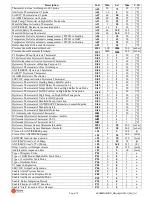
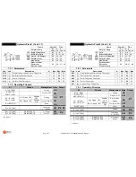
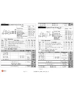
Description
Cod.
Min
Set
Max
U.M.
Thermostat to close Air Damper on S1 probe
A05
20
75
90
[°C]
Antifreeze Thermostat on S1 probe
A06
-10
4
10
[°C]
SAFETY Thermostat on S1 probe
A07
60
80
90
[°C]
ALARM Thermostat on S1probe
A08
80
90
99
[°C]
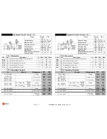
High Temp. Thermostat on high Buffer Tank probe
A23
20
95
95
[°C]
Manifold Pump Activation Thermostat
A33
5
20
50
[°C]
ANTIFREEZE Thermostat on manifold probe
A34
-10
4
10
[°C]
Manifold Safety Thermostat
A35
60
120
180
[°C]
Manifold Protection Thermostat
A36
60
140
180
[°C]
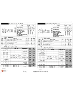
Temperature Delta for automatic management of PWM1 in Heating
A80
1
20
50
[°C]
Temperature Delta for automatic management of PWM1 in DHW
A81
1
15
50
[°C]
Temperature Delta for automatic management of PWM2 in Heating
A82
1
20
50
[°C]
Buffer-Manifold Differentail Thermostat
d02
5
20
2
[°C]
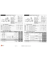
Pressure Sensor Minimum threshold
Pr01
500
3000
500
[mbar]
Pressure Sensor Maximum threshold
Pr02
2000
3000
500
[mbar]
P1 Fireplace Pump Hysteresis Thermostat
IA01
0
2
20
[°C]
P2 Deviator Valve Hysteresis Thermostat
IA02
0
2
20
[°C]
Boiler Integration Activation Hysteresis Thermostat
IA03
0
2
20
[°C]
Hysteresis Thermostat of Heating Pump on S1
IA04
0
2
20
[°C]
Hysteresis Thermostat to Close Air Damper
IA05
0
2
20
[°C]
ANTIFREEZE Hysteresis Thermostat
IA06
0
1
20
[°C]
SAFETY Hysteresis Thermostat
IA07
0
1
20
[°C]
ALARM Hysteresis Thermostat
IA08
0
1
20
[°C]
SERVICE output activation Hysteresis Thermostat
IA09
0
2
20
[°C]
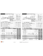
Hysteresis Thermostat of Heating Pump on Buffer probe
IA17
0
2
20
[°C]
Hysteresis Thermostat of DHW Boiler Thermostat on S2
IA18
0
2
20
[°C]
Hysteresis Thermostat of Integr. Buffer Tank on High Buffer Tank Probe
IA19
0
2
20
[°C]
Hysteresis Thermostat of Buffer Comfort on High Buffer Tank probe
IA20
0
2
20
[°C]
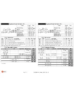
Hysteresis Thermostat of High Temp. on High Buffer Tank probe
IA23
0
2
20
[°C]
Hysteresis Thermostat of Valve for DHW priority
IA24
0
2
20
[°C]
Hysteresis Thermostat of Manifold Pump Activation
IA33
0
2
20
[°C]
Hysteresis Thermostat of ANTIFREEZE Thermostat on manifold probe
IA34
0
1
20
[°C]
Hysteresis Thermostat of Manifold Safety
IA35
0
2
20
[°C]
Hysteresis Thermostat of Manifold Protection
IA36
0
2
20
[°C]
S3 Ambient probe Hysteresis Thermostat
Ib01
0
1
20
[°C]
Differential Hysteresis Thermostat Fireplace - Buffer
Id01
1
1
5
[°C]
Differential Hysteresis Thermostat S3-S2
Id02
1
1
5
[°C]
Differential Hysteresis Thermostat S1-S3
Id03
1
1
5
[°C]
Hysteresis Pressure Sensor Minimum threshold
IP01
0
50
400
[mbar]
Hysteresis Pressure Sensor Maximum threshold
IP02
0
50
400
[mbar]
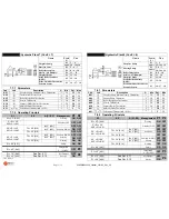
Time on for ANTIFREEZE pump
t 01
1
5
300
[s]
Time off for ANTIFREEZE pump
t 02
0
30
300
[min]
SHOWER function time duration
t 03
0
10
120
[min]
ANTISEIZE time “on” of Pump
t 04
0
20
99
[s]
ANTISEIZE time “off” of Pump
t 05
1
168
255
[h]
Delay time for Air Damper closure
t 06
0
10
120
[min]
Audible alarm suspension time
t 07
1
5
60
[min]
Type of Fireplace Probe
P01
0
0
2
n
Type of DHW Boiler/High Buffer Tank Probe
P02
0
0
2
n
Type of Low Buffer Tank Probe
P03
0
0
2
n
Type of Ambient Probe
P04
0
0
2
n
S3 Input Configuration
P05
0
0
1
n
SERVICE Output Configuration
P06
0
0
3
n
Enable Alarm Pressure Sensor
P07
0
0
1
n
Enable Antifreeze on Fireplace Probe
P08
0
1
1
n
Enable Antifreeze on manifold Probe
P09
0
0
1
n
Enable Boiler Integration Priority
P10
0
0
1
n
Enable Fireplace SAFETY Function
P11
0
1
1
n
Enable “Start” Function of Air Damper
P12
0
0
1
n