


Pag. 3/15
0CAR6IN019124_Manual_GLH110_Rev_0.3
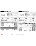
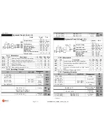
PUMP P1 FUNCTIONING TEST
When the controller is OFF, prolongued pressure of
K3
key:
P1
output is activated for as long as the key is pressed and the display will show
tSt1
PUMP P2 FUNCTIONING TEST
When the controller is OFF, prolongued pressure of
K4
key:
P2/P4
output is activated for as long as the key is pressed and the display will show
tSt2
SERVICE OUTPUT
P4 SERVICE output is programable from the Installer MENU by using parameter
P06
:
P06 = 0 DISABLED
: the output does not work.
P06 = 1 THERMOSTAT
: the output is activated if the temperature of
S1
probe is above Thermostat
A09.
P06 = 2 GRILL
: press
K1
key to turn on/off the output.
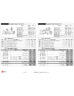
P06 = 3 AIR DAMPER
: this output is used to manage an Air Damper to adjust for Combustion Air Flow.
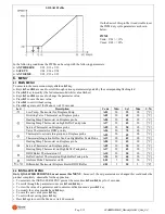
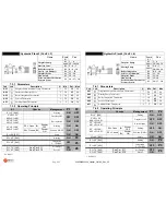
AIR DAMPER
To make use of the Air Damper function set parameter
P06 = 3
If the output is ON the Air Damper will be Open, if the output OFF the Air Damper will be closed.
The Air Damper will stay Open as long as the temperature of S1 probe is below
A05
Thermostat. The Air Damper will close
when the temperature is above this Thermostat.
If
P12 = 1
the
Start Manual
function is enabled:
If S1 Temperature is below
A01
, the Air Damper will Close. During the Ignition phase of the Fireplace, by pressing
K1
key
the Air Damper will Open manually (the output corresponding Led will flash). When the Temperature falls below
A01
,
Thermostat after
t06
time the Air Damper will close automatically.
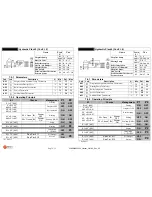
PROBE TYPE
The controller can manage NTC10K, NTC100K and PT1000 type of probes, which can be configured by using parameters
P01
,
P02
,
P03
and
P17
of the Installer MENU.
Fireplace Probe:
P01 = 0 → NTC10K; P01 = 1 → NTC100K; P01 = 2 → PT1000
DHW Boiler Probe/ Tall Buffer : P02 = 0 → NTC10K; P02 = 1 → NTC100K; P02 = 2 → PT1000
Short Buffer Probe:
P03 = 0 → NTC10K; P03 = 1 → NTC100K; P03 = 2 → PT1000
Ambient Probe:
P04 = 0 → NTC10K; P04 = 1 → NTC100K; P04 = 2 → PT1000
Manifold Probe:
P17 = 0 → NTC10K; P17 = 1 → NTC100K; P17 = 2 → PT1000
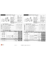
S3 INPUT CONFIGURATION
Parameter
P05
can be enabled to mange the following:
P05 = 0, S3
input
=
DISABLED
P05 = 1, S3
input
=
PRESSURE SENSOR
P05 = 2, S3
input
=
AMBIENT SENSOR
P05 = 3, S3
input
=
AMBIENT SENSOR
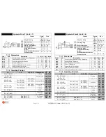
PRESSURE SENSOR
If
P05=1
pressure sensor management is enabled on probe
S3
.
If
P07=1
pressure sensor errors are enabled:
If Water Pressure <
Pr1
dispaly shows
PrLo
+ audible signal.
If Water Pressure >
Pr2
dispaly shows
PrHi
+ audible signal.
PROBE SENSOR/AMBIENT THERMOSTAT
Parameter
P05
can be setup to enable the management of the Probe Sensor/Ambient Thermostat
If the Ambient Temperature
S3
>
b01
or the Ambient Thermostat is
Open
(
Led flashing
) and there is
NO
DHW request
The Shutter is closed
The hydraulic/plumbing plants with a Buffer tank; if the Ambient Temperature is
S3
>
b01
or the Ambient Thermostat is
Open
the
Heating Pump will be turned off (deactivated)
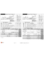
SHOWER
(
P13=1)
if used in specific hydraulic/plumbing plants where it is required, it can be enabled by pressing
K2
key for 3 sec
:
The display shows
T03
time (minutes) giving (DHW) Domestic Hot Water priority;
K3
and
K4
keys increase /decrease the duration
Wait 5 seconds to save and exit from this setup.
To exit without saving press
K1
key.
T03
time is signaled by
led flashing, giving priority to DHW production based on the type of hydraulic/plumbing plant
in use.
This function is over when
T03
time has expired.
By pressing again
K2
key
If the temperature of
S1
Probe is greater than
A07
Safety Thermostat:
And
T03=0
, the shower function can be disabled by pressing
K2
key.