


-7-
MAIN ROTOR /
主旋翼機構組裝
Bag B
HME3-3B
SET SCREW M3×3
無頭內六角螺絲
M3×3
BK1203
Linkage Ball(ø3.8)
連接頭
(ø3.8)
No.
1
2
3
4
Qty
2
2
2
2
Material No.
BK1499
BK1500
BK1203
HSP16-6N
Description
METAL FLYBAR CONTROL ARM-1
METAL FLYBAR CONTROL ARM-2
LINKAGE BALL(ø3.8)
COUNTERSUNK SCREW M1.6×6
名稱
金屬穩定翼轉臂
-1
金屬穩定翼轉臂
-2
連接頭
(ø3.8)
圓頭十字螺絲
M1.6×6
No.
5
6
7
Qty
1
2
2
Material No.
BK1410-1
HME3-3B
BK1413
Description
SUS FLYBAR ROD
SET SCREW M3×3
FLYBAR PADDLE(GREEN)
名稱
不鏽鋼穩定桿
無頭內六角螺絲
M3×3
穩定翼
(
綠
)
T22
T22
CA
T22
T22
(1)
(6)
(6)
(5)
(7)
(7)
(2)
(4)
(3)
CA
83mm
83mm
70mm
70mm
54mm
HSP16-6N
Countersunk Screw M1.6×6
圓頭十字螺絲
M1.6×6
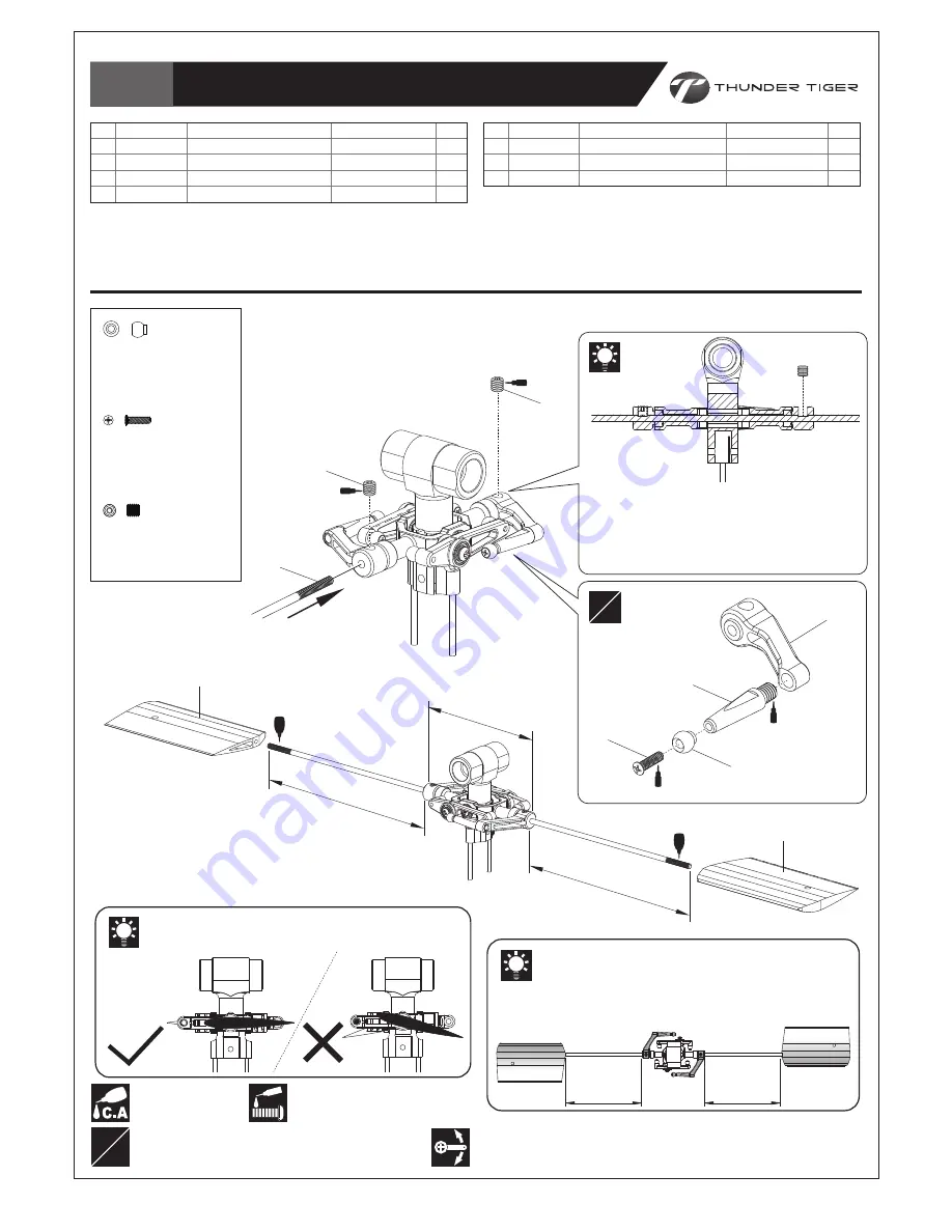
Assemble left and right side the same way
左右側組件相同
L R
Ensure the leading edges of the Paddles are
toward the same side to the Metal Flybar Control
Posts.
確認穩定翼前緣與穩定翼控制轉臂方向相同。
Thread the Paddles onto the Flybar Rod, equal the
length to the Flybar Control Arms of each side.
旋上穩定翼於穩定翼桿上,確認兩側的穩定翼至控制臂
距離相等。
Line up the Paddles with the Flybar Control Arms.
對正穩定翼與穩定翼控制臂呈水平狀態。
Ensure smooth, non-binding movement when assembling
確認組件靈活度
Apply threadlocker
使用螺絲防鬆膠
Secure all screws shown on this page with a drop of thredlocker.
本頁顯示之螺絲請使用適量防鬆膠鎖固。
Line up the hole of the Flybar Control Arm
and the flat spot of the Flybar Rod when
securing the screw.
安裝平衡桿時,請確認對正穩定翼控制臂上鎖
固孔位與平衡桿上平面凹槽。
L R
Apply C.A Glue
使用快乾膠黏合