

2
3
Kit Contents:
Floats
Description
Q'ty
2
4
1
9
1
1
1
1
1
1
Floats
3.
the
Sand the glue area of the plug and
hole on the
float, next epoxy the plugs in place. Note the plug
w/Rudder Bush will be at left float which you drill an
extra hole for the brass tube mount.
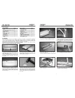
1.Locate two identical Floats, drill 5mm holes on the
molded dots for four nylon Mounting Brackets(Left/2,
Right/2) at least 30mm( 1-3/16 ).
Place the Brass Tube Mount as indicated position then
drill 3mm(1/8 ) hole through the mount and to the float.
Next enlarge the hole on float to 5mm(13/64 ) and drill
at same depth.
”
”
”
2.Trial fit the plastic sleeve and make sure the depth is
just flush with the sleeve, remove the sleeve and
roughen the plastic sleeves with sandpaper( 150 grit).
Glue all the sleeves in place with epoxy. Note that the
holes are faced up . Make sure there is no epoxy inside
the hole of the sleeve.
ASSEMBLY
4.Locate the Water Rudder, Rudder Shaft and Rivet.
Insert the rivet then use hammer to secure the rudder in
place. Note: The rivet has a hole on one end, suggest to
place a Phillips Screw Driver on the hole then slightly hit
the driver so the rivet will break evenly. Next hit the rivet
directly until water rudder is secured firmly but still can
swivel back .
5.Install the water rudder in the plug w/bush then secure
the Steering Arm in place with 2.6x8mm wood screw.
6.As floats are always in water, use care to apply the
decal or it will be pilled easily.
Clean the surface of the floats before applying the decals.
7. Remove nose gear then install the Nose Brace on the
firewall with the screws.
Float
Mounting Bracket (Left/2, Right/2)
Brass Tube Mount
Plastic Sleeve
Plug
Plug w/Rudder Bush
Steering Arm
Water Rudder
Rudder Shaft
2.9x13mm Rivet
1
2
9
1
1
2
4
1
2.8M Wire
Tension Spring
3x15mm Wood Screw
Cross Bar
Nose Brace
4x30mm Socket Head Screw
4mm
Locknut
2.6x8mm
Wood Screw
Description
Q'ty
8.Secure all mounting brackets on the floats with
3x15mm wood screws. Next Secure the Nose Brace
and Main Landing Gear on the brackets. Use Socket
Head Screws 4x30mm for Nose Brace and 4x40mm for
Main Landing Gear also secure the cross bar to the Main
Landing Gear.
9.
Drill two small holes around 2mm( 5/64 ) at the left
side of the fuselage as indicated in the illustration.
”
10. Locate the Angled Brass Tubes and mount, install
the tubes in the mount then secure the whole assembly
on the float with 3x15mm wood screw.
4
2
2x5mm Brass Tube
Angled Brass Tube
2
4x40mm Socket Head Screw
1
Sticker
Before assembling the float set we suggest to remove all the flash by using 200-grit sandpaper.
The float set is not necessary to paint. If you would like to paint the float and (or) other parts, this is the time
to do it. Any fuel-proof paint and do not damage ABS material may be used. Please be aware of the
dangers that the use of some paints brings, if any doubt contact your paint supplier.
Before Painting carefully sand every part using 400 grit sandpaper, then use a mixture of water and a few
drops of washing up liquid to remove any trace of dirt from the parts.
We do not recommend painting the bottom of the floats.
“
”


