Thunder Power TP820CD Instruction & Operation Manual Download Page 32

32 


the top line (starting with #1 on the left and ending with #4 on the right) and 5-8 on the bottom line.  
Also, any cells that show 0.00V are not applicable or are not being measured due to a balance 
connector connection issue.  So if you’ve connected a 4S battery but see voltages for only 3 cells be 
sure to check the connections accordingly. 
 

Also, in some cases the voltage for cell #1 will not show correctly in relation to the rest of the 
cells in the battery if only the balance connector is connected to the balancer/charger.  If you 
encounter this issue, keep the balance connector connected then also connect the main power 
leads to the charger.  Then, use the +/– buttons to scroll away from and back to the individual 
cell voltage data screen to refresh the measurement.

  Now the voltage for cell #1 should also 

show correctly. 
 

Please also note that while only the second (hundredths) place after the decimal is shown due 
to the space available on the screen (in order to show voltages for up to 8 cells on a single 
screen), the charger is measuring and calculating the voltages/balance by using to the third 
(thousandths) place.  This means when you see a cell at 3.80V and another at 3.82V the cells 
are likely as close as 3.804V and 3.816V but the values on the screen are being rounded up 
and down accordingly. 


Real-Time Input Voltage and Output Voltage Data 

 
This is the real-time input and output voltage (per the selected port) data.  You can see the voltage 
from the input power source as well as the voltage at the output if any battery is connected to the 
charger leads.  This is particularly helpful if you’d like to determine the voltage of the battery that is 
connected without starting a charge/discharge process. 
 
Please also note that while only the second (hundredths) place after the decimal is shown the charger 
is measuring the input/output voltage by using to the third (thousandths) place.  This means the 
input/output voltage reading may appear to move up and down slightly, however, the input/output 
voltage is indeed stable. 
 

Internal Temperature Data 

 
The Internal TEMP data displays the internal temperature of the charger.  This can be particularly 
helpful if the other port is in use so you can see if the charger’s temperature is approaching the 
Temperature Cutoff even before starting a charge/discharge process on the currently inactive port. 
 

ERROR MESSAGES AND TROUBLESHOOTING 
 

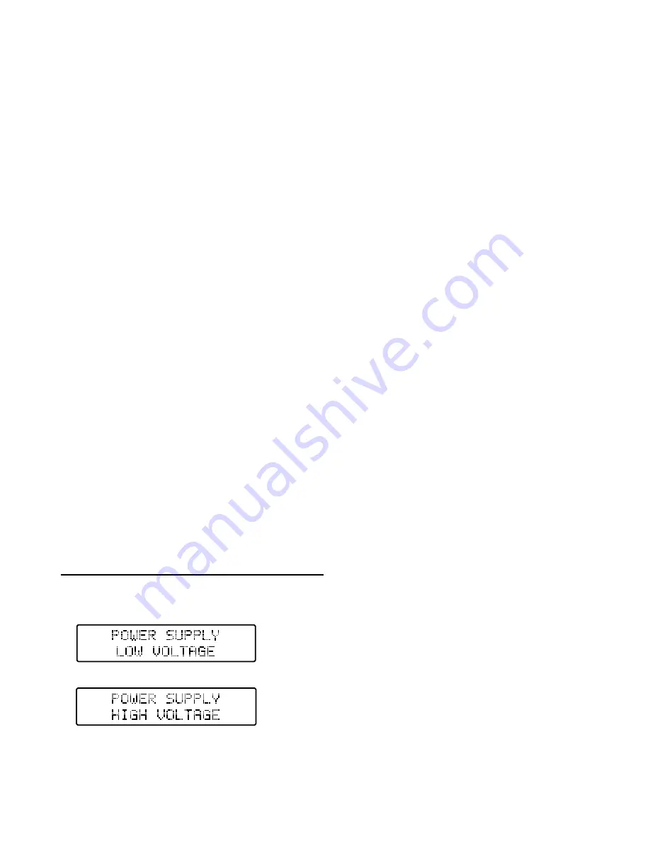
In some cases you may encounter the following error messages: 


This error message indicates that the 
voltage from the input power source/supply 
is too low (below 10.0V). 


This error message indicates that the 
voltage from the input power source/supply 
is too high (above 28.0V). 

Summary of Contents for TP820CD

Page 1: ...1 DUAL PORT HIGH POWER MULTI CHEMISTRY CHARGER DISCHARGER CYCLER BALANCER SYSTEM INSTRUCTION OPERATION MANUAL www ThunderPowerRC com...

Page 2: ...Memory Profiles 12 Battery Chemistry Type 12 Battery Cell Count 12 Battery Capacity 13 Charge Current Rate 13 Balancing ON OFF for LiPo LiIon LiFe batteries 14 Delta Peak Sensitivity for NiCd NiMH ba...

Page 3: ...acity Limit 27 Safety Timer 27 Temperature Cutoff 28 Key Beep 28 End Beep Duration 28 Temperature Unit 28 DATA VIEW MODE 28 Battery Internal Resistance 29 To Measure Battery Internal Resistance 30 To...

Page 4: ...injury CAUTION Attempting to charge batteries different that those specified in this manual can result in excessive heat and other related product malfunctions which can lead to property damage and o...

Page 5: ...rge two 5S 5000mAh batteries one on each port simultaneously at rates up to 4C or two 6S 5000mAh batteries at rates more than 3 5C to have a complete 10S or 12S 5000mAh battery setup charged in as lit...

Page 6: ...cumbersome parallel charging and a more powerful power supply Advanced Storage Mode function for LiPo LiIon LiFe A123 batteries will automatically charge or discharge as needed to achieve storage leve...

Page 7: ...DC output Input Current Max The maximum input current can be set from 10 0 40 0A in order to prevent damage to the power source and or charger This means you can limit the maximum current the charger...

Page 8: ...n may not show and instead only part of the default Charge Mode screen will show This will typically happen when connecting the charger to a power source that is already on so we suggest powering down...

Page 9: ...s and higher minimum 16 AWG at rates up to 10 amps and minimum 18 AWG at rates up to 5 amps Please also be certain to connect all batteries with the proper polarity as marked on the faceplate label an...

Page 10: ...d is equipped with balance connectors compatible with all 2S 7 4V to 8S 29 6V LiPo LiIon LiFe batteries equipped with Thunder Power and JST XH balance connectors And in the event that you must connect...

Page 11: ...to select and validate values settings for options that can be changed using the buttons to change before and during charging discharging Pressing and holding the ENTER button also allows you to start...

Page 12: ...arge discharge the battery Instead please contact the manufacturer of the battery for more information first To select the correct battery chemistry type while on the Charge Mode screen simply press t...

Page 13: ...at the 1C rate especially if you are not confident in taking advantage of and or aware of the max charge rate capability of the battery you ll be charging Or if you are interested in charging at a rat...

Page 14: ...th built in balancers for LiPo LiIon LiFe A123 cells batteries and you should ALWAYS use the balancers when charging LiPo LiIon LiFe batteries for maximum safety and battery performance longevity The...

Page 15: ...charge process had been completed ended To adjust the delta peak sensitivity value while on the Charge Mode screen simply press the ENTER button six times The value will begin to flash and you can use...

Page 16: ...ounded up and down accordingly If you press the button a second time you ll again see the elapsed time as well as the internal temperature of the charger and the peak voltage the battery has reached t...

Page 17: ...ged to within approximately 0 05V or less after the charge process is complete for each From there the batteries are ready to use in series and we suggest as with all LiPo batteries to discharge no mo...

Page 18: ...tively short lead lengths can make this somewhat difficult Now the most important step is to ensure that the balance connector labeled as Group A on the battery is connected to the extension balance c...

Page 19: ...aving the two ports attempt to charge balance the halves together simultaneously Also due to potentially slight differences in the condition performance of each battery we suggest checking to ensure t...

Page 20: ...is automatically calculated by the charger based on the estimated voltage of the battery being discharged and the cell count you have selected 3 6V per cell for LiPo batteries So in most cases it is n...

Page 21: ...the correct battery chemistry type and cell count in the Charge Mode then also the correct discharge current rate and voltage cutoff in the Discharge Mode connect the battery to the charger properly...

Page 22: ...to run even when the internal temp has reached near ambient temperature If this happens you can power the charger off then on again and the fans will remain off until the next charge discharge proces...

Page 23: ...see the elapsed duration of the current charge or discharge process the capacity that s been charged into discharged from the battery the charge discharge current rate and the voltage of the battery A...

Page 24: ...voltage is above approximately 3 85V per cell the battery to approximately 3 85V per cell and for LiFe batteries to approximately 3 3V per cell For NiCd NiMH batteries the charger will automatically...

Page 25: ...Discharge Cycle or Storage Mode screens by pressing the MODE button once From there you can use the buttons to scroll through the available screens menus accordingly It s also important to note that...

Page 26: ...oltage up to 3 80V per cell for the same reasons as noted for LiPo batteries above Also please note that this adjustment is to allow for advanced fine tuning calibration of the charge end voltage howe...

Page 27: ...th the Battery Capacity function found in the Charge Mode see the Battery Capacity sub section of the Charge Mode section for more information adds an additional level of safety to help ensure that ev...

Page 28: ...eep The Key Beep function setting allows you to turn the audible beep associated with key button presses ON or OFF To turn the beep ON or OFF simply press the ENTER button once then use the buttons to...

Page 29: ...ly decrease throughout the first 25 100 cycles while often stabilizing for hundreds more cycles after Resistance of the Wire Leads Connector Because the IR is being measured through the battery and ch...

Page 30: ...le That said in many cases if the IR of a given cell battery increases by 50 from when new it will typically offer noticeably less performance However especially in lower discharge rate applications s...

Page 31: ...during charge processes the cells are still likely relatively close in actual resistance However significant variations for example a cell that measures 200 higher in IR than other cells in the same...

Page 32: ...16V but the values on the screen are being rounded up and down accordingly Real Time Input Voltage and Output Voltage Data This is the real time input and output voltage per the selected port data You...

Page 33: ...with the balance connector connection and or a significant imbalance This error message indicates that the wrong battery type has been selected For example you have a LiPo balance connector connected...

Page 34: ...discretion of TPRC This warranty does not cover cosmetic damage or damage due to acts of God accident misuse abuse negligence commercial use or modification of or to any part of the Product This warra...

Page 35: ...for return of electronics including chargers balancers motors etc not including batteries Do not cut or remove any factory installed wire leads connectors etc All electronics MUST be packed well withi...

Page 36: ...TPRC Non Warranty Repair or Replacement Should your Product s not be repairable or replaceable under warranty it they may be eligible for repair or replacement at a discount off the current purchase...

Page 37: ..._______________________________________________________________ _________________________________________________________________________________ ______________________________________________________...

Page 38: ...2011 Thunder Power RC 4720 W University Ave Las Vegas NV 89103 USA 702 228 8883 www ThunderPowerRC com Dynamite E flite and ParkZone are registered trademarks of Horizon Hobby Inc Rev 02 24 11 for V3...

Page 39: ...cted This is calculated using the discharged voltage of the battery i e 3 3V per cell for LiPo batteries so it is possible to set the charge current rate to the maximum rate possible And if you have s...

Page 40: ...T V 0 0 8 536V LiPo Charge 0 00 00 Input Voltage 15 000V LiPo Charge 0 00 00 Average Voltage 00 000V LiPo Battery Store CHG CAP 0mAH Discharge CAP 0mAH Cycle CHG CAP 0mAH 01 DCHG CAP 0mAH Cycle Mode S...

Reviews: