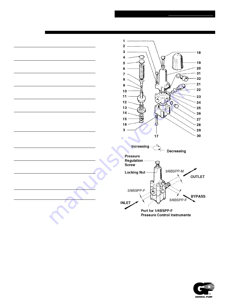
ThoroughClean P13C-36C Operator'S Manual Download Page 21

K7 Unloader Valve

NO.

PART NO.

DESCRIPTION

KIT NO.

QTY.

1.

92.2368.00

Nut

1

2.

99.3084.00

Screw

4

3.

96.7014.00

Washer

8

4.

90.3849.00

O-Ring

70

1

5.

36.3095.70

Spring Plate

1

6.

94.7466.00

Spring

1

7.

36.3094.66

Seat Valve

70

1

8.

90.5052.00

Anti-Extrusion Ring

70

1

9.

90.3820.00

O-Ring

70

1

10.

90.3582.00

O-Ring

70

1

11.

36.3097.02

Piston Assembly

70

1

12.

94.7464.00

Spring

70

1

13.

90.2766.00

Packing

70

1

14.

96.7215.00

Washer

1

15.

90.2565.00

Packing

70

1

16.

90.5063.00

Anti-Extrusion Ring

70

1

17.

99.3127.00

Screw

4

18.

99.3663.00

Screw

1

19.

36.3098.02

Optional Adjust. Knob

1

20.

36.3090.41

Upper Body

1

21.

Nipple

1

10.0078.70

K7.0, 3/8 BSPP, Ø3.0 mm

10.0078.70

K7.1, 3/8 BSPP, Ø3.0 mm 

10.0160.70

K7.2, 3/8 BSPP, Ø3.25 mm

10.0161.70

K7.3, 3/8 BSPP, Ø3.5 mm

22.

90.3833.00

O-Ring

70

1

23.

Nozzle

1

10.0076.66

K7.0, Ø2.2 mm

10.0077.66

K7.1, Ø2.5 mm

10.0162.66

K7.2, Ø2.75 mm

10.0163.66

K7.3, Ø3.0 mm

24.

90.3823.00

O-Ring

70

1

25.

90.3863.00

O-Ring

70

1

26.

36.3091.41

Central Body

1

27.

98.2041.00

Cap Screw

2

28.

90.3585.00

O-Ring

70

2

29.

90.3871.00

O-Ring

70

1

30.

36.3092.41

Lower Body

1

31.

96.7380.00

Washer

1

32.

Nipple

1

36.3117.70

K7.0, 3/8 BSPP

36.3116.70

K7.1, 3/8 BSPP

36.3118.70

K7.2, 3/8 BSPP

36.3119.70

K7.3, 3/8 BSPP

Repair Kit 70
Includes No.'s:

4, 7, 8, 9, 10, 11, 12, 13, 

15, 16, 22, 24, 25, 28, 29

INSTALLATION
Select an unloader appropriate for the
pressure and flow of your system (see
specification chart). This unloading valve is a
flow-through design and should be mounted
on the discharge line of the pump in any
position (horizontal or vertical) which allows
easy access to the adjusting bolt. A pressure
gauge should be installed on either side of the
port of the unloader to accurately read
pressure during adjustment. Minumum 5%
bypass is required for proper operation.

WARRANTY
General Pump accessories are warranted by the manufacturer to be free from
defects in material and workmanship  Period of warranty shall be 90 days from
date product is received by original buyer. Liability of manufacturer under the
foregoing warranty is limited to repair or replacement at the option of
manufacturer of that product which according to the manufacturer's
investigation was deemed defective at time of shipment. Damage resulting
from neglect, abuse, tampering or misapplication voids this warranty. This
warranty is in lieu of all other warranties, expressed or implied, including any
warranty of merchantability and/or any and all other obligations or liabilities on
the part of the manufacturer.

PARTS LIST

K7

GENERAL PUMP

A member of the Interpump Group

300110  Rev. B

2-95

GENERAL PUMP     

1174 N

ORTHLAND

D

RIVE

•  M

ENDOTA

H

EIGHTS

, MN  55120

P

HONE

: (651)454-6500  •  F

AX

: (651)454-4524  •  e-mail: [email protected]  •  www.generalpump.com

Summary of Contents for P13C-36C

Page 1: ...R 30C TO P20R 43C T P20R 43C TO Index Page 2 Technical data Specifications 3 4 Installation Start up 5 Operating Tips Shutting down Regular Checks 6 7 Maintenance Schedule 8 9 Trouble Shooting Guide 1...

Page 2: ...50 psi 18 lpm Set up de rated pressure flow 1600 psi 14 lpm 3500 psi 17 lpm 2600 psi 18 lpm 3000 psi 18 lpm Or 3500psi 18 lpm 3000 psi 18 lpm Vs 3000 3500 psi Nozzle size at set up pressure 15060 1504...

Page 3: ...To Start Ensure that the main RED ON OFF switch is switched to OFF Ensure the Choke is ON Moved fully to the left when engine is cold Ensure Fuel is OPEN Fuel lever moved all the way to the right Now...

Page 4: ...at comfortable revs set to the power requirement for the pump pressure and flow DO NOT ALTER REMEMBER Check for leaks and Oil Levels DAILY OPERATING CLEANING TIPS 1 Using a Fan Jet first blast off hea...

Page 5: ...ure safety protective gear is used and in good state of repair Ensure Safety MEDIC ALERT Card is handy Prolonged by pass Leaving the unit in prolonged by pass machine is switched on but trigger is not...

Page 6: ...90 YES YES YES 10 Strip and Refurbish pump Replace Plunger Rod Oil Seals 3 pump Replace Brass Valves 6 pump Replace various seals 3 pump Replace Ceramic Piston Plungers if cracked or worn 3 pump Only...

Page 7: ...swivels H P Hoses are usually uneconomical to repair Replace as necessary Remember to check filters regularly and clean under running water The correct procedure for replacing the filter mesh in the s...

Page 8: ...system Check suction hose Increase diameter size for bigger supply Damaged ceramic plunger Replace Plunger SHORT PLUNGER SEAL LIFE Excessive pressure and or temp in the pumped water Check the tempera...

Page 9: ...ton Check Replace OIL IN PUMP EMULSIFIED CONTAMINATED BY WATER water in the oil Water Blasted into Pump via Breather Cap during Cleaning Exercise Care H P Piston Seals Worn or Check and Replace Seal P...

Page 10: ...lost through by pass valve and only small increase in pressure is achieved doing this Lost of waster horse power When orifice is reduced the PSI will rise and then by pass valve will dump thinking the...

Page 11: ...r Always carefully test on a small area first ALWAYS WEAR PROTECTIVE GEAR PPE i e Head face eye protection wet weather gear boots and gloves which is particularly important where hot water or aggressi...

Page 12: ...ling the safety tag off the machine and taking it with you to the doctor Tell the doctor what type of project task was being performed at the time of the injury making special note of any chemicals th...

Page 13: ...cement or refund for a major failure and compensation for any other reasonably foreseeable loss or damage You are also entitled to have the goods repaired or replaced if goods fail to be of acceptable...

Page 14: ...y period THIS WARRANTY WILL NOT APPLY TO Any part component that has been subject to misuse negligence accidental damage improper or inadequate maintenance or improper storage Any part that has been s...

Page 15: ...n the required flow of the pressure pump specification and suitable power supply outlet for electrical units where applicable 8 No responsibility will be taken for late delivery day due to unforeseen...

Page 16: ......

Page 17: ...spring Molla valvola 6 20 0604 00 Valve cage Gabbia valvola 6 21 1400 02 Washer Rosetta 6 5 8 4 22 1802 07 Hexagonal screw Vite M6x18 8 4 23 0205 01 Shaft protector Protezione albero 1 24 0500 09 Open...

Page 18: ...52 0500 15 Motor flange Flangia motore 1 Part available Particolare disponibile in kit only solo in kit Part available Particolare disponibile in kit also anche in kit Part Number Description Codice...

Page 19: ......

Page 20: ...3 6 6 10 8 GPM 0 3000 PSI Features all stainless and brass internal parts New design reduces sensitivity to entrapped air No external moving parts or springs Unique barb and flow balance design provid...

Page 21: ...3 15 16 22 24 25 28 29 INSTALLATION Select an unloader appropriate for the pressure and flow of your system see specification chart This unloading valve is a flow through design and should be mounted...

Reviews: