KATflow 150
5 Commissioning
5.2
Diagnostics
Diagnostic screens can be viewed directly during measurement using the
3/DISP
and
1/NEXT
keys, or through the menu structure.
5.3
Display settings
Customer specific settings for data to be displayed can be achieved using the ap-
propriate menu items to select units for the top, middle and bottom lines.
5.3.1 Main PV
The main Process Value (PV) is the primary measurement data, and is usually dis-
played as the Middle Units.
5.4
Output configuration
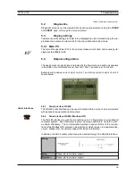
The assignment of output slots is detected by the flowmeter, and will be as appears
in the table in the "In/Output" menu - first line = Slot 1, second line = Slot 2 etc.
Example with passive current input on slot 1 and active current output on slot 2
shown below :
5.4.1
Serial interface RS 232
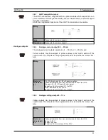
The RS 232 serial interface can be used to transmit data on-line or to communicate
with peripheral equipment and computers.
5.4.2
Serial interface RS 485 / Modbus RTU
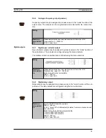
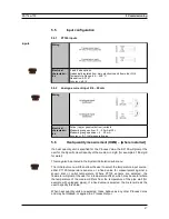
The RS 485 interface is used for connecting up to 32 flowmeters to a centralised
computer system. Each flowmeter is given an unique address to be able to com-
municate effectively. The communication protocol used conforms to the conven-
tions of the Modbus RTU protocol, a description of which is given in a separate doc-
ument. Please refer to customer support for further information.
In addition, the ASCII printer output can also directed through the RS 485 interface.
Wiring
Setup
Please refer to customer support.
Operation
Please refer to customer support.
34
Serial interfaces
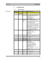
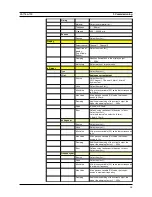
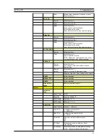
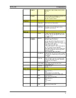
Table 6: Firmware menu structure

