LFS4100
Chapter 4: Set-Up
Page 10
TTN047498-D01
Chapter 4
Set-Up
1.
Unpack the desktop computer and set it up using the included instructions from the computer
manufacturer. If the operator is right handed, the computer should be set up to the right of the operator. If
the operator is left handed, the computer should be set up to the left of the operator.
2.
Unpack the LFS4100 and place it on a workbench. Make sure not to damage any components of the
LFS4100 during handling of the workstation. Lift by the built-in handles on the side of the system.
Remove the labeled transport block from the base of the camera tower.
3.
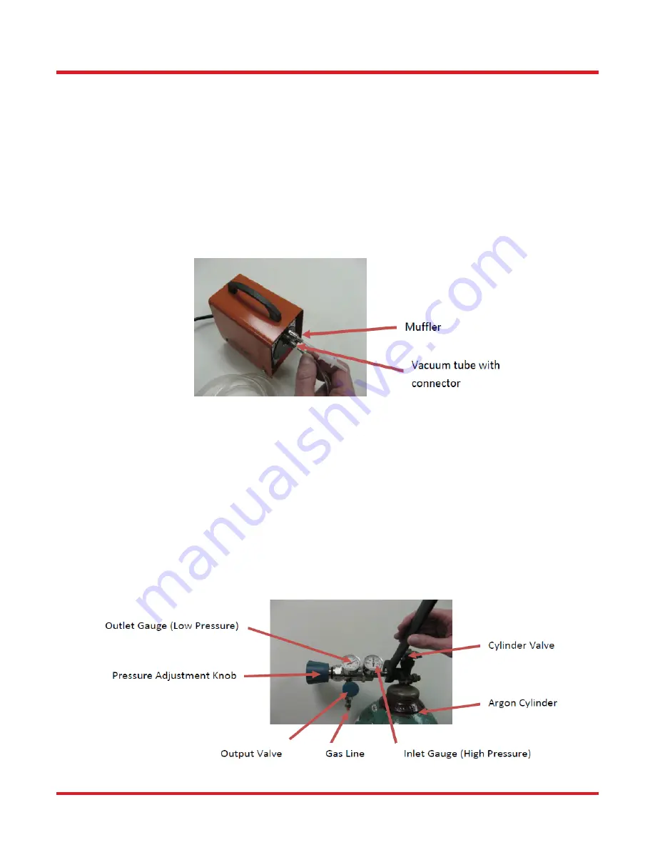
Connect the external vacuum pump:
a.
Connect the muffler to the top connector of the vacuum pump
b.
Using the included tube, connect the bottom connector on the vacuum pump, labeled "VAC," to the
connection labeled "VACUUM" on the back of the LFS4100.
Figure 11 External Vacuum Pump for Bottom Fiber Holder Inserts
4.
Use the included IEEE-1394 firewire cable to connect the camera to the port on the LFS4100 labeled
"CAMERA" (6-pin side) and to the firewire port on the computer (4-pin side).
Note:
The computer and the LFS4100 have to be powered off before connecting and disconnecting the
camera firewire cable.
5.
Use the RS-232 serial communication cable to connect the port labeled "SERIAL COMMS" on the back of
the LFS4100 to the computer’s serial communication connector (see instructions from computer
manufacturer). Tighten the screws on both sides of the cable.
6.
Install the supplied CGA-580 gas regulator to the gas tank as shown below, using the manufacturer-
supplied operating and safety instructions. (
NOTE:
a European DIN 477 Number 6 fitting is supplied as
required in European markets. An adaptor may be required to allow connection of the supplied CGA-580
output port to the gas tank fittings in other areas or countries).
Figure 12 Gas Tank Regulator and Gas Line
Summary of Contents for Vytran LFS4100
Page 1: ...LFS4100 Fiber Splicer User Guide...
Page 44: ...www thorlabs com...


