background image

LDC401 & LDC401A Automated Cleavers


Chapter 3: Description


Rev B, July 19, 2017 

Page 5


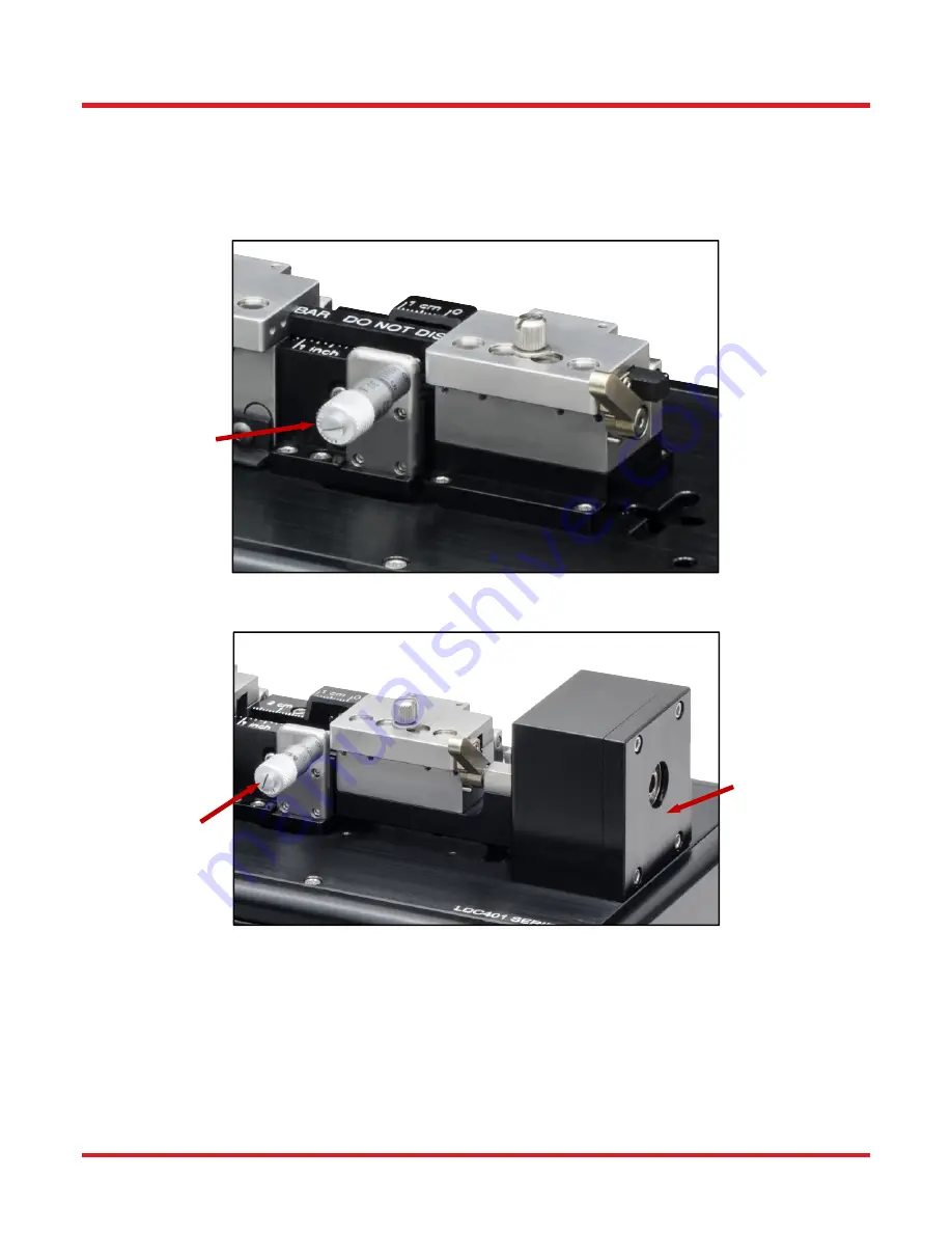
Both the LDC401 and LDC401A include a micrometer that can back up the fiber during cleaving, particularly useful 
for large-diameter fibers. The LDC401A incorporates a Rotary Stage that can rotate the right Fiber Holding Block 
in order to twist the fiber and produce an angle cleave. Please note that it is not possible to add Angle-Cleaving 
capability to the LDC401. 

The illustrations below show the differences between the LDC401 and LDC401A. 


Figure 4 

LDC401 Cleaver with Micrometer Backstop 


Figure 5 

LDC401A Cleaver with Micrometer Backstop and Rotary Stage for Angled Cleaves

Micrometer 

Backstop 

Micrometer 

Backstop 

Rotary Stage 
for Angle 
Cleaves 

Summary of Contents for Vytran LDC401

Page 1: ...LDC401 LDC401A Automated Cleavers for Fibers with 80 m to 1 25 mm Claddings User Guide...

Page 2: ......

Page 3: ...d Thumbscrews 11 7 4 Stripping the Fiber 13 7 5 Loading the Fiber 14 7 6 Cleaving the Fiber 15 7 7 Unloading the Fiber 16 7 8 Changing the Fiber Holding Block Inserts 17 7 9 Specialty Cleave Process 1...

Page 4: ...1 9 5 3 Auto Parameter 41 9 5 4 Blade Service 42 9 5 5 Insert Selector 42 9 6 Log Out 43 9 7 Exit Close 43 9 8 Parameter Description 43 9 9 Parameter Limit 45 9 10 Setup Tips Cleaving a New Fiber 46 C...

Page 5: ...mbol Description Direct Current Alternating Current Both Direct and Alternating Current Earth Ground Terminal Protective Conductor Terminal Frame or Chassis Terminal Equipotentiality On Supply Off Sup...

Page 6: ...The Cleave Blade should never touch the fiber on the initial fast move towards the fiber or damage to the blade could result WARNING Do not place your fingers between the left Fiber Holding Block and...

Page 7: ...ed properly the cleavers can produce both flat and angled LDC401A only cleaves with high quality end face finishes For detailed information on the Tension and Scribe technique please refer to Chapter...

Page 8: ...separately Bottom inserts purchased separately Canvas Bag Figure 2 The LDC401A with Included Accessories If you are missing any of the accessories or need replacements please contact the distributor f...

Page 9: ...t can rotate the right Fiber Holding Block in order to twist the fiber and produce an angle cleave Please note that it is not possible to add Angle Cleaving capability to the LDC401 The illustrations...

Page 10: ...ial Set up 1 Plug in the AC power cord The power supply accepts an AC input of 100 240 VAC 47 63 Hz 2 Connect the AC power cord to the external power supply 3 Connect the DC power cable to the unit 4...

Page 11: ...Type B plug into its socket on the back of the unit 7 Plug the USB Type A plug on the first USB cable into its socket on the back of the unit 4 2 Power Up 1 Turn on the Cleaver using the ON OFF Rocke...

Page 12: ...Controller include User Password setup User accessibility control to safeguard against accidental changes to parameters and user files Language selection Voice notification USB communications setup A...

Page 13: ...rpendicular to this Direction When configured and operated properly both cleavers are capable of producing cleaves with high quality end face finishes 6 1 Specialty Fiber Cleaving Processes Two additi...

Page 14: ...the fiber is positioned and securely clamped in the FHBs an automated Cleave Process can be initiated by pressing the Start button Parameters that can be adjusted using the Tablet Controller are in b...

Page 15: ...ieces of Fiber after a Cleave It is critical that the Cleave Tension be set appropriately for the fiber being cleaved If the tension is set too low the fiber may not cleave and the diamond blade could...

Page 16: ...2 m 208 m N A Yes VHF160 Transfer Bottom VHD250 Bottom 177 m 320 m N A Yes VHF250 Transfer Bottom VHD400 Bottom 279 m 519 m N A Yes VHF400 Transfer Bottom VHD500 Bottom 346 m 795 m N A Yes VHF500 Tran...

Page 17: ...the lids with a stick or pulling them out with a rare earth magnet It is prudent to mark one side of the magnets before removal so the orientation and position are easily identified After completing w...

Page 18: ...in the downward position and carefully lower the left hand FHB lid 5 With the lifting lever in the downward position the lid will not contact the fiber and the fiber is still free to move Set the Cle...

Page 19: ...reached the left hand FHB will stop moving e The Cleave Blade will move forward towards the fiber over the Blade Offset Pre Cleave Advance distance CAUTION The Cleave Blade should never touch the fibe...

Page 20: ...e to dispose of the cleave discard properly as these shards can be very sharp 6 Check that no debris is left behind in the FHB V grooves or on the lid clamping surfaces After the vacuum turns off the...

Page 21: ...p insert CAUTION Do not change the top insert without a bottom insert in place the top insert can get stuck in the lower channel 1 Loosen the four 4 set screws accessible from the back of the FHB lid...

Page 22: ...fitment of both inserts in the FHB together Re tighten the set screws until they are snug Do NOT over tighten Figure 18 Changing the Bottom Inserts It is important that both inserts in the FHBs fit to...

Page 23: ...activate the Subcritical Process open the Parameter Select screen select the Sub Critical Cleave Process parameter and select Enable When enabled three additional parameter values must be specified T...

Page 24: ...t the Micrometer Backstop just Touches the Fiber To use the Micrometer Backstop load the fiber in to the unit in the normal way but do not initiate a cleave immediately Rotate the micrometer until it...

Page 25: ...closing properly and the fiber from being fully clamped It is particularly important to make sure that the bottom insert V groove surfaces and the top insert clamping surfaces are free of debris and o...

Page 26: ...event possible damage to the Cleave Blade and retract the Micrometer Backstop Figure 22 Cleaning the Cleave Blade The Cleave Blade should be cleaned using a cotton tipped swab wetted with acetone or i...

Page 27: ...sition the blade to a new section of the diamond edge 4 Re tighten the clamping screws These should not be over tightened Figure 23 Screws Used in Height Adjustment After adjusting the height of the C...

Page 28: ...a unit and consists of the diamond Blade tip which is permanently mounted to a stainless steel base with a round reduced diameter shank WARNING Use great care when working near or handling the Cleave...

Page 29: ...cleave position 4 Loosen the set screw in the top of the Cleave Arm one full turn counter clockwise using the 0 035 hex key provided Figure 26 Set Screw and Cleave Arm 5 Insert the 0 035 hex key thro...

Page 30: ...assembly 1 Locate the 3 32 hex key provided with the tool kit 2 Loosen the two clamping screws located at the front of the cleave block assembly turning counter clockwise one full turn 3 Turn the heig...

Page 31: ...C Main Screen is displayed From here the User can start a cleave view edit Parameters select items on the toolbar A Status Bar B Tool Bar C Start Button D Parameter View Edit E LDC Widget Figure 28 LD...

Page 32: ...ffset will require the motor to be re homed after uploading The controller will ask if it s ok to home Be sure that there is no fiber clamped in the machine or any other obstruction that may cause the...

Page 33: ...ce the LDC401 to the tension stage Figure 32 Cleave Screen Extended Vacuum The LDC401 will wait until the user is ready to start the cleave or repeat load fiber Note that the user can return to the LD...

Page 34: ...Peck Indicator is also displayed Figure 35 Cleave Screen Tension and Peck When the fiber is cleaved the tension will drop to zero and the Cleave Peck Indicator remains on screen The LDC will wait for...

Page 35: ...ws 10 Tablet The controller application VytranCX exe is launched automatically on Windows startup After a few seconds of displaying a master Home Screen a discovery process is launched which detects a...

Page 36: ...k if none and three icons to indicate file status unprotected or read only current user access status and USB connection Figure 40 LDC Main Screen Status Bar The control button on the LDC Main Screen...

Page 37: ...screen when something important is happening such as reading parameters from the LDC and uploading new parameters to the machine Figure 43 LDC Main Screen Toast Messagers The toolbar provides access t...

Page 38: ...e controller defaults to No Password Full Permission enabled If a password has been setup and entered the user can quickly log out using Log Out from the toolbar A password is required only if one has...

Page 39: ...n effect until the user touches Toolbar Log Out Figure 48 Toolbar New Password Screen 9 3 2 Access Permissions Tablet Controller can be setup to prevent unauthorized access of files and parameters whi...

Page 40: ...as read only If a read only file contains an error it s possible to correct it If a password has been setup the user must enter it before being allowed to change User Access Permissions 9 3 3 Voice No...

Page 41: ...ction is independent of computer locale or computer language packs installed Complete translations are available in English French and Russian and Chinese more will be available in the future In the e...

Page 42: ...a missing connection Tablet Controller will normally auto detect the correct USB serial Comm Port to communicate with the LDC 9 4 Files Files are opened saved or saved as from Toolbar File The user is...

Page 43: ...d folder and files can only be saved in that folder Touch the file in the list to select to it for opening Swipe the list to scroll up or down 9 4 2 Save File As Figure 56 Save File As Screen To selec...

Page 44: ...ge communication with LDC401 Motor Manipulation Tools FHB Cleave Blade Rotation Auto Parameter recommendation of best theoretical parameter values for a given fiber cleave angle Blade Service T Insert...

Page 45: ...ouch and slide the slider button to move the motor Below the slider are individual buttons for small step manipulation in either direction and a stop button In the case of the left FHB the user is giv...

Page 46: ...rameters needed to manage blade setup Touch an item in the list to edit provided the user has sufficient Access Permissions When the blade is in its Service Position the Home button is displayed when...

Page 47: ...aving the rest of the parameters set to their default values Parameter Description Fiber Diameter The diameter of the fiber cladding to be cleaved Other recommended values are derived from this Cleave...

Page 48: ...s that the Cleave Blade moves away from the fiber during each blade oscillation Typically this parameter is set to 80 steps Increasing this parameter and correspondingly the Cleave Forward Steps param...

Page 49: ...Typically the Post Scribe Pause is set to 1 3 seconds This is enough time for the scribe to propagate and cleave the fiber if the scribe was too large Re Tension Pause seconds This parameter is the pa...

Page 50: ...it strikes the fiber before it starts to oscillate raise the RHS FHB Lid immediately to prevent damage to the blade then check that Blade Offset is correctly setup are different sized fibers cleaved p...

Page 51: ...Section 10 1 should be used to select the appropriate Inserts for each holding block Top Inserts The table below summarizes the top Fiber Holder Inserts that are available from Thorlabs Item Side 1 Mi...

Page 52: ...A No Insert Selection Guide The table on the following page indicates the maximum and minimum diameters that can be accommodated by different combinations of Top and Bottom Inserts It also indicates...

Page 53: ...2193 2429 6 229 2278 2513 78 313 VHE25 2500 m 2270 2505 172 64 2355 2590 87 148 2439 2675 2 233 2609 2844 167 402 VHE30 3000 m 2692 2944 256 4 2777 3029 171 81 2946 3198 2 250 Legend Best Fit Second B...

Page 54: ...of our fiber is going to sit 50 m above the Bottom Insert surface since it is 50 m larger than the fiber that the Bottom Insert was designed for 800 750 50 4 Holding blocks designed for fibers less t...

Page 55: ...ontrolled Fiber Holding Blocks Internal Vacuum Pump for Easier Loading Up to 9 inHg 4 4 psi of Pressure V Groove Inserts Available Separately Below Power 12 5 VDC 5 A Provided by External Power Supply...

Page 56: ...em needs to be returned to Thorlabs for service or evaluation The illustrations below show the correct way to re pack the LDC401 or LDC401A Please ensure that the bottom of the box is taped securely b...

Page 57: ...rs In addition to specifying these new parameter values two existing parameter values may require adjustment These are Cleave Tension and Cleave Oscillation Counter peck cycles Experimentation will be...

Page 58: ...below fiber Raise Cleave Blade Housing Blade passes above fiber Lower Cleave Blade Housing Blade reaches fiber but does not cleave it because fiber is large and FHB separation is large Use Micrometer...

Page 59: ...other Thorlabs products such as Pure OEM products that means assemblies to be built into a unit by the user e g OEM laser driver cards Components Mechanics and optics Left over parts of units disassem...

Page 60: ...urope thorlabs com Scandinavia Thorlabs Sweden AB Bergfotsgatan 7 431 35 M lndal Sweden Tel 46 31 733 30 00 Fax 46 31 703 40 45 www thorlabs com Email scandinavia thorlabs com France Thorlabs SAS 109...

Page 61: ......

Page 62: ...www thorlabs com...

Reviews: