


Page 18
20381-D02
Single- and Dual-Axis Scanning Galvo Systems for Large Beam Diameters
Chapter 4 Operation
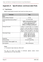
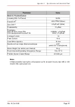
4.1 General Operation
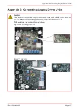
1) Connect the system as described in Section 3.2.
2) Apply power to the driver boards.
3) Input a command signal to each driver board to obtain the desired behaviour.
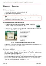
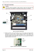
4.2 External Enabling of the driver board
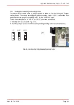
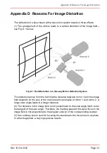
1) The drive electronics can be configured for external enabling by
placing a jumper across pins 2 and 3 of JP4.
2) Once this has been done the user can enable or disable the drive electronics by
applying a 5V CMOS signal to J7 pin 4.
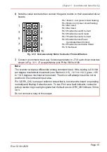
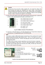
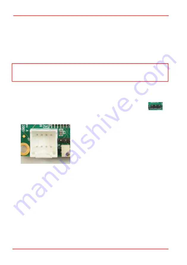
Fig. 4.1 J7 Command Input Connector Pin Identification
If a logic high or no signal is applied the drive electronics will be enabled. If a logic low
signal is applied then the driver will be disabled.
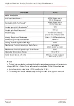
4.3 Using a DAQ Card
Typically, users will deploy a DAQ card with DAC analogue outputs in order to drive
the servo drivers supplied with the galvos. The minimum recommended
specifications for the DAC outputs are:-
Dual bipolar -10V to 10V DAC analogue output channels (differential).
DAC clocking frequency higher than 20kS/s (Kilo Samples/Second), higher sampling
frequencies like 100 kS/s are recommended (inputs have a 7 kHz low pass filter).
16 Bit DAC resolution and low out impedance (<= 50
Note
After powering the boards, there may be a delay of up to 10 seconds before the
motors start to follow the command signal.
1 2 3
1 2 3 4
8 7 6 5
Pin 1 Command Input +ve
Pin 2 Command Input -ve
Pin 3 No Connect
Pin 4 External Enable
Pin 5 -12V Output
Pin 6 +12V Output
Pin 7 Ground
Pin 8 Ground
Summary of Contents for GVS011
Page 40: ...www thorlabs com ...


