Rev 19 Oct 2020
Page 23
5.2 Galvanometer Faults
The driver electronics monitor numerous signals to ensure the scanners operate
safely and the fault protection circuitry will normally prevent any damage.
However, the user should be aware that the galvanometer may become permanently
damaged if the system becomes unstable (manifested by a screeching noise, self
excitation and unpredicable movement of the scanner). In addition the user should
also be aware that the system has no protection against the galvanometer scanners
overheating, and it is left to the user to ensure that they are fitted to an adequate
heatsink (see Section 3.1.1.).
It is worth noting that a fault state may be triggered on applying power to the driver
boards and the power amplifier will be disabled. However in this case the board will
commence normal operation after a delay of a few seconds. The table below shows
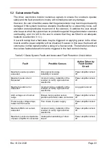
the various faults states which can be triggered in the fault control circuitry.
Table 5.1 Galvo System Faults and Associated Fault Protection Circuit Action
Fault
Possible Causes
Action Taken by
Fault Control
Circuit
Maximum scanner position
exceeded
Drive signal too large,
instability of scanner
Power amplifier turned
off
Maximum peak current
Exceeded
Incorrect tuning, instability of the
scanner or overly vigorous drive
waveforms
Power amplifier turned
off
Maximum postion error
exceeded
Incorrect tuning, instability of the
scanner or overly vigorous drive
waveforms
Loop gain reduced
AGC voltage out of normal
range
Broken motor position sensor,
problem with motor cable connection
Power amplifier turned
off
Power supply voltage drops
below minimum value
Poor choice of power supply
Power amplifier turned
off
Maximum RMS coil current
exceeded
Incorrect tuning, instability of the
scanner or overly vigorous drive
waveforms
Power amplifier turned
off
Maximum junction temperature
of power amplifier IC exceeded
Inadequate heatsinking of driver
board
Power amplifier turned
off
Summary of Contents for GVS011
Page 40: ...www thorlabs com ...


