16
HA0278T Rev H Dec 2016
Chapter 3
3.4
Front Panel Controls and Indicators
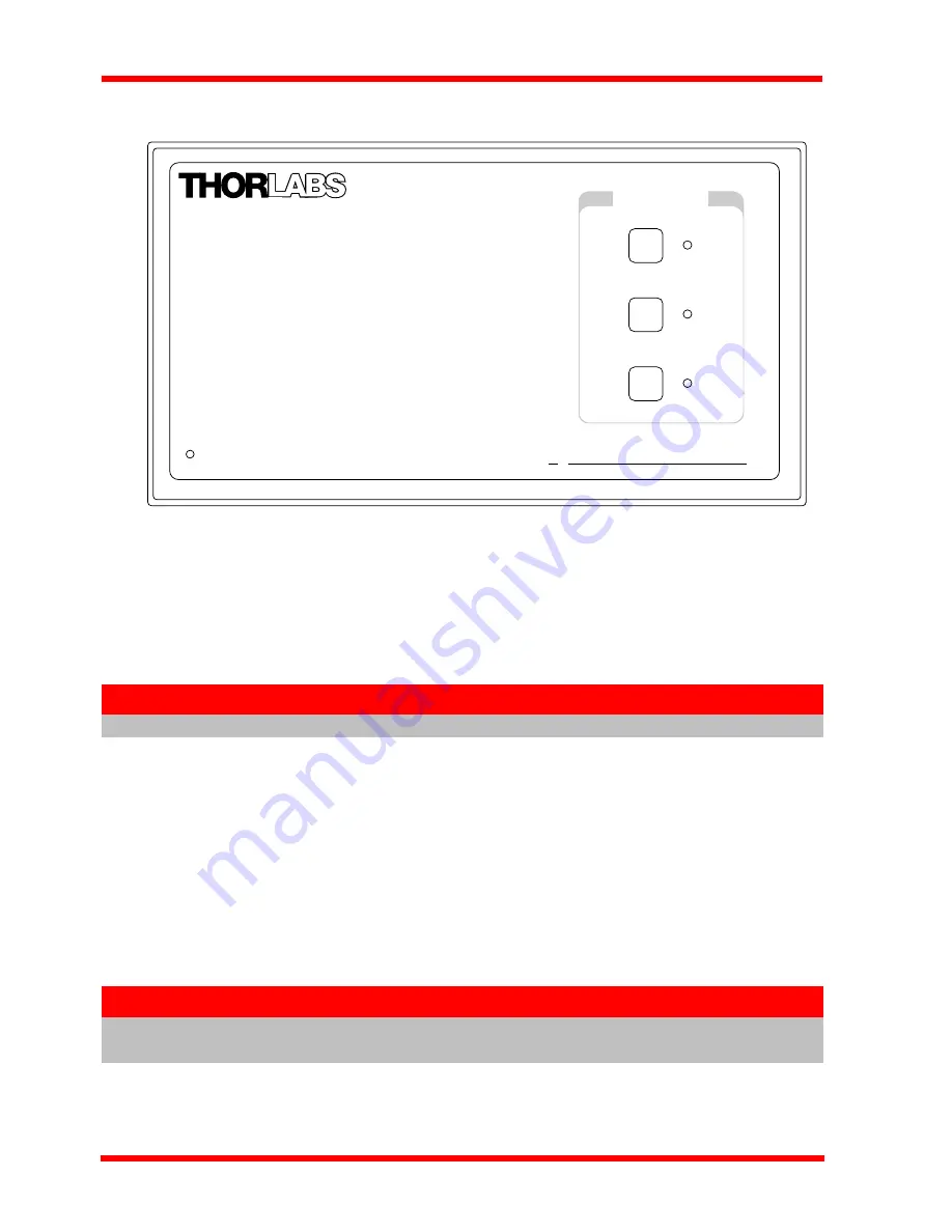
Fig. 3.2 Front panel controls and indicators
Power LED
– Indicates that power is applied to the unit.
CHANNEL ENABLE buttons
– Used to enable/disable channel functionality. The
associated LED is lit when the channel is enabled. Disabling the channel allows the
motor actuator to be moved manually.
3.5
Connecting The Hardware
1) Perform the mechanical installation as detailed in Section 3.2.
2) Install the APT Software - see Section 3.1.
3) Connect the stepper motor actuator to the Controller unit - see Section 3.3.4.
4) Connect the Controller unit to the power supply - see Section 3.3.1.
5) Connect the PSU to the main supply and switch ‘ON’.
6) Connect the Controller unit to your PC.
7) Windows
TM
should detect the new hardware. Wait while Windows
TM
installs the
drivers for the new hardware - see the Getting Started guide for more information.
Note
On BSC202 units, the Channel 3 LED is not used.
Note
The USB cable should be no more than 3 metres in length. Communication
lengths in excess of 3 metres can be achieved by using a powered USB hub).
Power
apt
Precision Motion Controller
CHANNEL ENABLE
1
2
3


