Scientific Grade Digital Video Camera
Chapter 4: Setup & Installation
ITN000089-D02, Rev H
Page 18
4.3.
Connecting the Camera
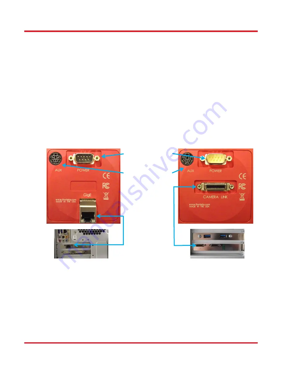
To connect the camera, follow the steps and refer to the diagram below.
1. With the power supply turned off, connect the DE-9 from the power supply to the DE-9 on the back of the
camera. The connector on the camera is labeled “POWER”.
2. Connect the auxiliary cable (
optional, ordered separately
) into the port on the camera labeled as “AUX”.
3. Connect the interface cable, either a Gigabit Ethernet (GigE) or a Camera Link, based on your camera
model.
-
If you are utilizing a Cat5e Gigabit Ethernet (GigE) Cable
: Connect the Ethernet cable to the port
on the camera labeled “GigE”. Connect the other end into the port of the Intel® Gigabit CT PCI
Express desktop adapter, installed in the computer.
-
If you are utilizing a Camera Link Cable
: Connect the camera link cable into the port labeled
“CAMERA LINK”. Connect the other end into the port of the EDT VisionLink F4 camera link card,
installed in the computer. Always connect to the port closest to the mother-board of the
computer. In Figure 2 below, this would be the left most connector labeled “0” – your computer
orientation may vary.
Figure 2
Diagram of Connectors on Camera (Left shows GigE configuration, Right shows Camera
Link configuration)
DB-9 Power Connector
Auxillary Cable Port
Ethernet
Cable Connection
Camera Link
Cable Connection


