Connections and initial set up
14
The connections proposed on page 4 permit the rapid connection of your DMR and ensure
optimum sound, visual quality (RGB) and standards. Depending on the sockets available on your
other devices or to benefit from the maximum performance of your DMR you may make other
connections.The DMR has other sockets for this purpose.
1 2
7
6
3
5
4
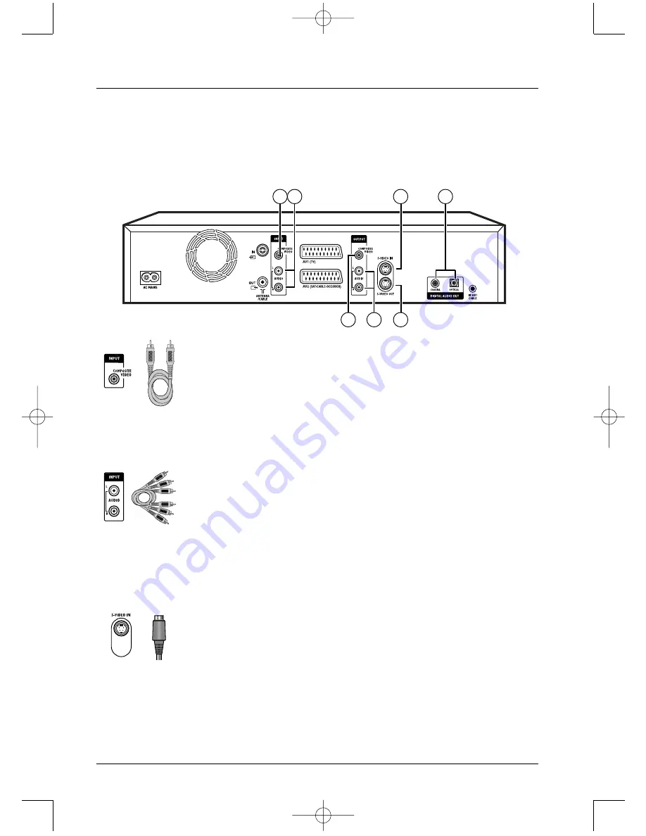
Sockets and cables (inputs)
1 – Video in - Composite (CVBS) (COMPOSITE VIDEO INPUT)
The yellow video socket also known as composite video (or CVBS): the
image quality provided by this socket is less better than all the other video
sokets. Only use this socket if all the other sockets are already in use.
2 - Audio inputs (INPUT L, R)
The analogue sound of an operating device (television set or amplifier) can be
input via the 2 Audio sockets L and R of your DMR. If you do not use the
recommended connection, i.e. the Peritel (Scart) socket, you must, as well as
the video connections (CVBS or S-VIDEO) connect the outputs Audio L and
R of the operating device to the Audio L and R inputs of your DMR.
Note: the audio sockets and cables are generally identified by a colour code (red for
the left channel and white for the right).
3 - S-Video input (Y/C) (S-VIDEO IN)
The S-Video signal is of a lesser quality than that of the RGB signal supplied
by the Peritel (Scart) socket.The S-Video signal however gives a better image
quality than the composite video socket (C) since black and white (Y) is
separated from colour in the video signal.
Note: do not forget to connect the audio cables since the S-Video cable transmits
only images, not sound.
RCA sockets and
cables for analogue
L and R audio
signal.
RCA socket and
cable for CVBS
Video signal, also
called Composite.
Ushiden socket and
cable for Y/C Video
signal, also called
S-Video.
DTH7500_en 4/07/03 16:55 Page 14


