background image

Getting Started

EN

5

Digital Connections

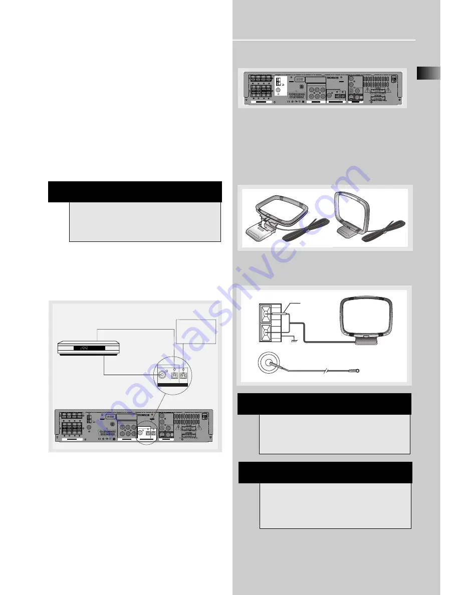
If you have a SAT receiver DVD player or CD player with a
digital output, you can make use of an optical digital con-
necting cord (not supplied) or coaxial digital connecting
cord (not supplied) to carry the audio portion of the signal
and enjoy Dolby Digital or digital stereo sound quality. One
optical or coaxial cable is needed for each SAT receiver,
DVD player or CD player. When optical or coaxial cable is
used, the analog audio cables are still needed if recording
through a tape or VCR is desired. This receiver provides one
optical and one coaxial digital input for the connection of
your components. Please connect your components (e.g.
DVD, SAT or CD) to the appropriate digital inputs and
select the appropriate source (see below).

Read instructions carefully when connecting components to
the receiver.

Digital In Jacks can accept Dolby Digital (AC-3), or PCM sig-
nals when compatible components are connected.

Connecting the Antennas

The AM and FM antennas connect to the AM and FM ter-
minals on the system’s back panel. 

They must be hooked up in order to receive clear reception.

AM Loop Antenna and FM Indoor Antenna

1. Uncoil the AM Antenna wire.

2. Press down on the Antenna tab to open the terminal
(Refer to the illustration on the bottom of page 6)

SAT / DVD / CD Player 

COAXIAL DIGITAL IN (AUDIO)
Connect to coaxial digital output 
of DVD, CD, SAT or other 
compatible devices.

OPTICAL DIGITAL IN (AUDIO)
Optical Fiber Cable 
Connect to optical digital output of DVD, CD, 
SAT or other compatible devices.

SAT / DVD / CD 

COAXIAL

IN

OPTICAL

IN

S A T

OPTICAL

OUT

D I G I T A L   A U D I O

OPTICAL DIGITAL OUT  
Connect to recording 
device like CD, CDRW 
player, DVD recorder, 
mini disc etc.

SAT

CENTER

SUB

FRONT

REAR

L

R

L

R

AM LOOP

FM 75‰

Manufactured under licence from Dolby Laboratories.
"Dolby", "Pro Logic 2" and the double-D symbol are 
trademarks of Dolby Laboratories. Confidential
Unpublished Works. ' 1992-1997 Dolby Laboratories,
Inc. All rights reserved.

S P E A K E R S

A U D I O

D I G I T A L   A U D I O

V I D E O

V C R   I N

V C R   O U T

L

IN

OUT

R

VCR

COAXIAL

IN

OPTICAL

OUT

SAT

IN

SAT

IN

ME67

TV

POWER SOURCE: 230V     50Hz
RATED INPUT POWER: 300W
SECTEUR 230V     50Hz
CONSOMMATION NOMINALE: 300VA

Shock hazard - do not open! Keep dry!
Before opening disconnect power plug!
Risque de choc  lectrique ne pas ouvrir!
Vor  ffnen Netzstecker ziehen!
Vor Feuchtigkeit sch tzen!

Przed otwarciem obudowy wyjąć wtyczkę z
gniazda sieciowego

Attention:

Attention:
Achtung:

UWAGA:

230V    50Hz

MON

OUT

OPTICAL

IN

S A T

GND

HINT

• For FM reception, extend antenna to its full
length and arrange the Antenna at different parts
of the room until the reception is optimized.
•  For AM reception, rotate the antenna 
horizontally to get better reception.

AM LOOP

FM 75

White

GND

CENTER

SUB

FRONT

REAR

L

R

L

R

AM LOOP

FM 75

Manufactured under licence from Dolby Laboratories.
"Dolby", "Pro Logic 2" and the double-D symbol are 
trademarks of Dolby Laboratories. Confidential
Unpublished Works. © 1992-1997 Dolby Laboratories,
Inc. All rights reserved.

S P E A K E R S

A U D I O

D I G I T A L   A U D I O

V I D E O

V C R   I N

V C R   O U T

L

IN

OUT

R

VCR

COAXIAL

IN

OPTICAL

OUT

SAT

IN

SAT

IN

ME67

TV

POWER SOURCE: 230V     50Hz
RATED INPUT POWER: 300W
SECTEUR 230V     50Hz
CONSOMMATION NOMINALE: 300VA

Shock hazard - do not open! Keep dry!
Before opening disconnect power plug!
Risque de choc électrique ne pas ouvrir!
Vor Öffnen Netzstecker ziehen!
Vor Feuchtigkeit schützen!

Przed otwarciem obudowy wyjąć wtyczkę z
gniazda sieciowego

Attention:

Attention:
Achtung:

UWAGA:

230V    50Hz

MON

OUT

OPTICAL

IN

S A T

GND

NOTE

Optical and coaxial cables carry only the audio por-
tion of the signal. A video connection must also be
established by connecting a video cable to the
(SAT) video input.

NOTE

Make sure the white wire on the AM loop antenna
is inserted into the top terminal.

Summary of Contents for DPL900VD - RADIO

Page 1: ...aylist The Jukebox is a true audio player installed on your PC It gives access to thousands of net radios available on the web today You can download music files encoded in MP3 from several Internet s...

Page 2: ...SO POWER ECO Thomson multimedia 46 47 quai A Le Gallo 92648 Boulogne Cedex FRANCE RCS nanterre B322 019 464 55199360 www thomson multimedia com...

Page 3: ...VOLUME OURCE SURROUND PRESET PRESET D I G I T A L mp3 PHONES BAND APP RPT PGM TEST TREBLE TUNE TUNE u s e r m a n u a l DPL900VD...

Page 4: ...LEAD INTO A MAINS POWER SOCKET POWER SUPPLY 230V It must not be connected to D C mains Note The mains lead of the set is fitted with a molded plug If the mains socket are not compatible or if for any...

Page 5: ...rols 10 Your Remote Control 11 Display 12 Switching On Off 13 Selection of Audio Video Source 13 Using the Remote to Control Additional Components 14 Advanced Sound Control Sound Enhancement Systems 1...

Page 6: ...T CAB VIDEO VCR one instruction book one safety leaflet one Quick Connection Guide One RCA Universal Remote Control RC800D Unpacking The Speakers one set of speakers including 1 set of left and right...

Page 7: ...he receiver near the top shelf of the stand so heated air rising from it will not affect other components EN 3 10 cm 4 10 cm 4 10 cm 4 VOLUME SOURCE SURROUND PRESET PRESET POWER D I G I T A L mp3 PHON...

Page 8: ...gnal When connecting S video cable a Composite video cable yellow RCA connector must also be used If you use a S video cable to connect any audio visual components to your DVD receiver you must also u...

Page 9: ...atories Dolby Pro Logic 2 and the double D symbol are trademarks of Dolby Laboratories Confidential Unpublished Works 1992 1997 Dolby Laboratories Inc All rights reserved S P E A K E R S A U D I O D I...

Page 10: ...ey Black Rear Speakers Brown Black Subwoofer Connect the speaker wire red black wire to the back of L R front speakers red black terminals and to the corresponding color terminals on the rear of the r...

Page 11: ...lded in order to prevent picture distor tion Front and center speakers provided with DPL900VD are magnetically shielded to protect your TV set It is not recommended to place the rear speakers near the...

Page 12: ...mounting is the only choice aim the speakers at each other A towards the front B or even towards the sidewalls C D Experiment with placement until surround sounds seem to envelop you rather than comi...

Page 13: ...hones are in place Once headphones are connected HEADPHONE DOWNMIX 2 CHANNEL will scroll on display This feature automatical ly converts multi channel outputs to 2 channel stereo for your listening pl...

Page 14: ...e next chapter in DVD mode only while playing 6 BAND APP RPT PGM In Tuner mode press to select between radio BANDS or press and hold to enter AUTOMATIC PRESET PROGRAMMING mode In DVD CD mode press to...

Page 15: ...the left and right arrow buttons beside OK button for adjustment angle selects different screen display angles if available 6 Adjustment Buttons Use arrows to move around on menus press OK to enter c...

Page 16: ...urrently in playback mode Currently in pause mode PARENTAL LOCK Parental lock is on and a password is required to view DVDs above a specific rating level TITLE Title number for DVD playback TRACK Trac...

Page 17: ...the display You will be able to have the sound and image transmitted by the VCR Example 2 Based on example 1 the VCR input is selected If SAT is selected image and sound from the SAT source will repl...

Page 18: ...e source to the amplifier 14 D I G I TA L PRO LOGIC INTRORANDOM L C R LS LFE RS DVD VCD CD MP3 NOTE 1 Your receiver has a built in tuner Just connect the appropriate antenna on the back of the receive...

Page 19: ...er speakers are used Dolby Digital The Dolby Digital mode lets you enjoy full digital surround from software processed in the Dolby Digital format Dolby Digital provides better sound quality and more...

Page 20: ...y PL II Music Dolby PL Dolby 3 Stereo Arena Jazz Theater Stadium Disco Stereo For Digital Signal Dolby Digital Dolby Digital Dolby 3 Stereo Stereo Default Settings The receiver will keep the last sele...

Page 21: ...The speaker being displayed can then be adjusted by using the LEFT or RIGHT arrows on the remote to desired level To get out of Test Tone just press SURROUND button and the setting will be saved Adva...

Page 22: ...right hand side of the display See diagram It is important to note however that not all Dolby Digital sources are encoded with the full complement of five chan nels plus LFE Speaker icons show how ma...

Reviews: