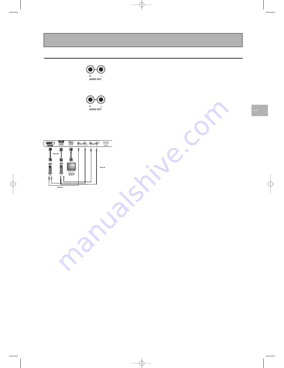
Connecting other equipment
EN
21
Connecting external amplified speakers
Connect the red (R) and white (L) audio out sockets located to the right
of the connector panel of the set respectively to the right and left
amplified speakers.
Connecting an amplifier
Connect the red (R) and white (L) audio out sockets located to the right
of the connector panel to the amplifier’s L and R inputs.
Note: The AUDIO OUT cinch sockets can be set to either
Fixed
or
Variable
audio
output levels. Please refer to page 15 for additional explanation on this feature.
Connecting a PC
Using RGB input
1.
Connect the 15-pin RGB connector on the PC to the RGB IN
connector located at the rear of the set.
2.
Connect the audio sockets on the PC to the R and L cinch audio in
DVI/RGB sockets on the rear panel of the set.
Using DVI input
1.
If your PC is equipped with DVI (Digital Visual Interface), connect its
DVI connector to the DVI IN connector located on the rear panel of
the set.
2.
Connect the audio sockets on the PC to the R and L cinch audio in
DVI/RGB sockets on the rear panel of the set.
Notes:
- If your PC only has a 3.5 mm jack, you will need to use a jack-to-cinch converter cable
for the audio connection.
- The RGB OUT connector on the TV set allows you to connect another RGB monitor. It
will display the same signal as the RGB IN signal source.
- The physical display resolution is a maximum of 640x480 dots when aspect ratio is set
to “4x3”, and 852x480 dots when set to “16x9”. If the PC’s display resolution exceeds
these maximum values, the TV set will have to artificially eliminate dots in order to fit
within the physical dot capability of the display; therefore, it is possible that the TV set
may not be able to show details with adequate clarity.
42pb120S4-en 2/07/04 11:32 Page 21


