


12
INSTALLATION
Fixing
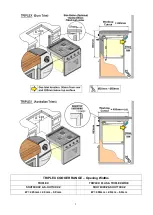
The appliance can be front or side fixed, holes are provided for either installation method.
Fixing screw positions are located on each side of the hotplate, two in each side trim. Screw
positions in each side of the oven opening allow the appliance to be either front or side fixed.
Connection
A ¼ BSP female connection is provided for gas inlet, on the rear of the appliance. It is
recommended that the appliance be connected by copper tubing, a rubber or hose connection
must not be used. After connection the appliance must be tested for soundness. The gas inlet
must be accessible with the appliance installed to ensure the installation is in accordance with
AS/NZS5601.
This appliance is suitable for use with
–
Universal LPG Only (2.75 kPa)
It is important that the regulator should be set to the correct pressure for the type of gas being
used. Excessive pressure must not be permitted.
If the flame on either the top burners or the grill shows a tendency to lift, it is probable that the
line pressure is too great. Should there be excessive yellow tips (resulting in sooting) then it is
probable that the line pressure is too low and, in either case, the burners should not be used
until the line pressure has been checked.
The burners on this appliance have fixed aeration and no adjustment is necessary.
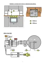
Connection - Electrical
The appliance is supplied with a power cord and plug which must be connected to a double
pole switched mains supply, with 3mm minimum contact separation at all poles.
Any excess power cord
MUST
be routed away from the appliance and not come into contact
with the appliance or hang loose into a lower compartment.
When satisfied with the appliance, please instruct the user on the correct method of operation.
If the appliance fails to operate correctly after all checks have been made, refer to the
authorised service provider in your area.
•
This appliance must be installed into an aperture, sealed off at either side
in order to prevent draughts from adjoining cupboards/vents. Ensure that
air vents and gas escape holes are kept clear, holes for cables and pipes
must be sized to minimize air leakage between compartments.
•
Under no circumstances should the ventilation hole exceed the maximum
specified. Low level vents in adjacent compartments are permitted.
•
After installation the appliance MUST be tested for soundness
•
Test ALL burners on high and low flame for flame stability.
•
The gas supply input pressure MUST not rise or fall significantly from
nominal when ALL appliances connected to the supply are operated
simultaneously.