pg. 7
4 . 1 . 2
4 . 1 . 2
4 . 1 . 2
4 . 1 . 2
4 . 1 . 2
MOUNTING CERAMIC CASING
MOUNTING CERAMIC CASING
MOUNTING CERAMIC CASING
MOUNTING CERAMIC CASING
MOUNTING CERAMIC CASING
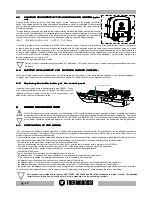
The next step, after positioning the heater, is to mount the ceramic casing as illustrated in the figures below.
Carry out the following operations:
- Unscrew the 2 knobs and remove the top cast iron cover.
- Mount the right ceramic panel supports (figure 2) following the procedure set out below:
Undo screws A and B and remove them momentarily. Fix support SID by firstly inserting the bottom folds on the seat of the heater base, next
re-insert and fasten screws A and B. Undo screws C and B and remove them momentarily. Fix support SSD then re-insert and fasten screws
C and D. Next screw in screws E and F provided. Screw in screws G and H provided.
Bend the tabs slightly (indicated in detail A of Figure 2) outwards from the heater. Next fix the side ceramics to the supports by securing them
to the bent tabs.
Next mount the left ceramic panel supports using the same procedure as described above for the right ceramic panel supports (Figure 2).
Next attach the side ceramic panels to the supports.
- Fix the lower front ceramic panel to its support (Figure 3) with the silicone provided; degrease and clean the ceramic panel support before gluing
the parts to ensure optimal adhesion. Leave the ceramic panel in the position illustrated in Figure 3 and wait 24 hours before handling it.
- Next fasten the lower ceramic panel to the heater following the instructions set out in Figure 4.
- Lastly position the top ceramic panel (Figure 1) and screw in the 2 knobs removed earlier.
Special care must be taken when handling and mounting the ceramics in order to prevent breakages that are not covered by
warranty. Small imperfections on the surfaces of the ceramics such as: dimples, shivering and slight colour variations are
normal characteristics of handcrafted ceramics which make each piece unique.
H
H
I
L
DETTAGLIO A
Figura
2
A
B
C
D
F
E
G
H
SID
SSD
Figura
1
3
Figura
4
Figura
Key
Detail A
Figure
LEGENDA
Dettaglio A
Figura
Summary of Contents for ECOTHERM 5000
Page 16: ...pg 16 ...
Page 17: ...pg 17 ...


